Transformer Voltage Regulation (%): How to Calculate and Improve It
تاريخ النشر: المؤلف: ليزا
Transformer voltage regulation is the percentage change in secondary voltage between no load and full load, with the primary held at its rated value. It explains why the same 2 kVA unit reads 118 V on the bench and 111 V with the heaters running. Small dry-type transformers between 100 VA and 10 kVA usually land between 3% and 6%; the cheap end can exceed 10%. If equipment behaves differently depending on what else is switched on, regulation — not the turns ratio — is what you are observing.
This guide is written for the person holding the multimeter: the formula and its two competing denominators, a worked calculation on a 2 kVA toroidal converter, a twenty-minute bench procedure, and the levers that actually move the number.
What Percentage Regulation Actually Measures
Hold the primary at rated voltage, measure the secondary with nothing connected, then load it to rated current and measure again. The drop between those readings, as a percentage, is percentage regulation. It is not a constant: it moves with load current, load power factor and winding temperature. A datasheet figure with no stated load and power factor is close to meaningless.
Two formulas, and why your numbers disagree
Transformer manufacturers and IEC 60076 / IEEE C57 practice use the full-load voltage as the base:
%VR = (Vno-load − Vfull-load) / Vfull-load × 100
Many textbooks, and most generator material, divide by the no-load voltage instead. Both are defensible; they are not interchangeable. A unit that sits at 240 V open-circuit and 220 V loaded gives 9.09% on the full-load base and 8.33% on the no-load base. Under one point apart — until you are checking a 5% contract limit, where the choice decides pass or fail. State the convention in every purchase specification.
Regulation is not efficiency, and not impedance
Efficiency is output power over input power, dominated by core and copper losses. Percent impedance (%Z) is the voltage needed to drive rated current through a shorted secondary, fixed by the design. Regulation is the voltage error a real load sees. A transformer can be 96% efficient and still regulate poorly: efficiency is one operating point, regulation is the slope between points. %Z is the ceiling — what the nameplate %Z value means covers that half of the story.
How to Calculate It: A 2 kVA Worked Example
You need two per-unit quantities, resistance r and leakage reactance x, both from the short-circuit test. Take a 2 kVA toroidal converter, 230 V to 115 V, 60 W of copper loss at rated current, measured short-circuit voltage 4.5%.
Step 1 — per-unit resistance. r = 60 W / 2000 VA = 0.030. Step 2 — reactance. z = 0.045, so x = √(0.045² − 0.030²) = 0.0335.
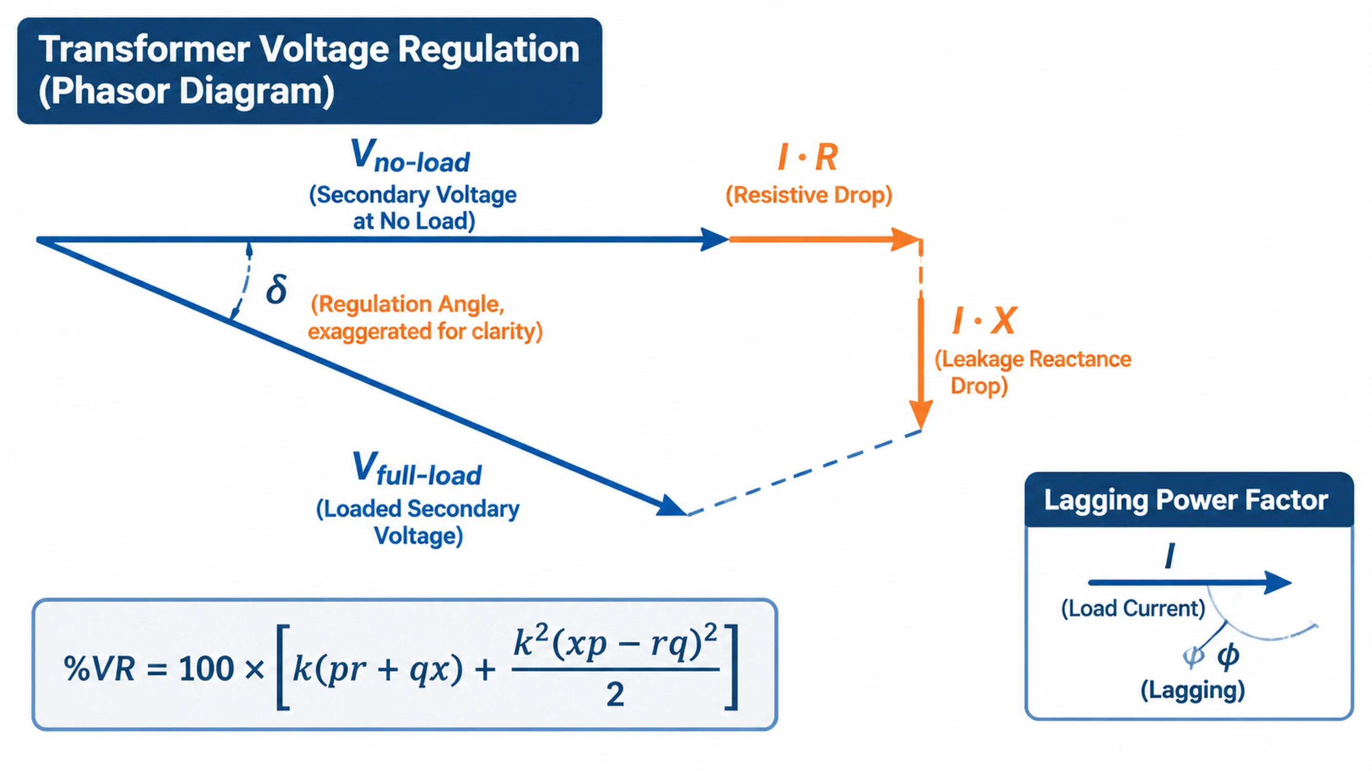
Step 3 — apply the exact expression, where p is load power factor, q = sin φ (positive lagging, negative leading) and k is the load fraction:
%VR = 100 × [ k(p·r + q·x) + k²(x·p − r·q)² / 2 ]
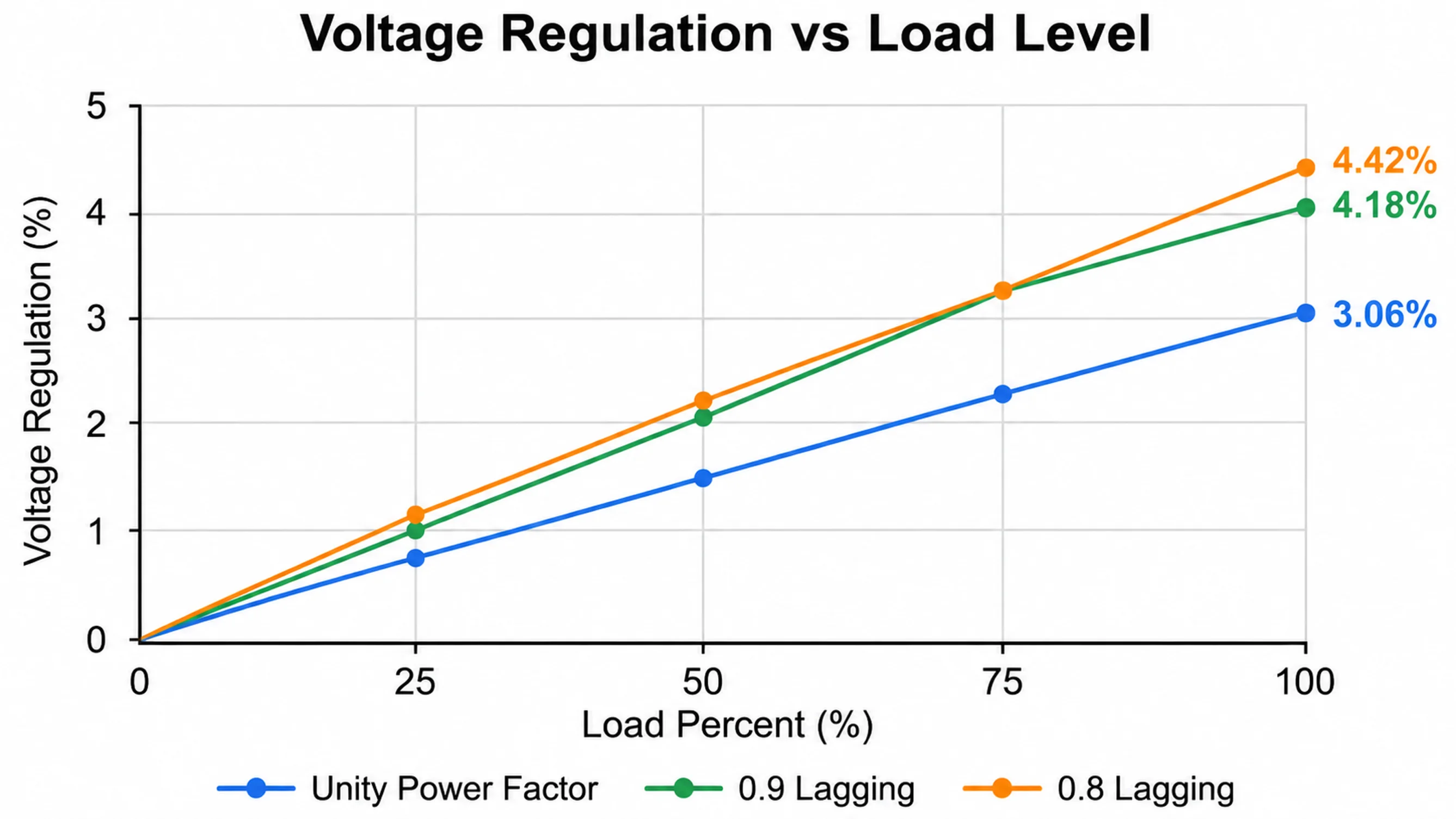
At full load and unity power factor the answer is 3.06%. At 0.8 lagging it rises to 4.42%. At 0.8 leading it collapses to 0.49%, and at 0.7 leading it turns negative at −0.19%.
Reading the result
Two things fall out that most online calculators never show. Regulation does not peak at the lowest power factor — it peaks where tan φ equals x/r. On a small transformer r and x are nearly equal, so the peak lands near 0.67 lagging, inside the range where real equipment operates. On a 1 MVA unit x/r is roughly 10 and the peak sits near 0.1 power factor, far outside normal service, which is why large transformers appear to regulate better than their %Z suggests. Practical rule: on small transformers assume regulation close to %Z, on large ones roughly two thirds of it.
Load power factor
Load level
%VR (full-load base)
Secondary at 115 V nominal
1.00
100%
3.06%
111.6 V
0.90 lagging
100%
4.18%
110.4 V
0.80 lagging
100%
4.42%
110.1 V
0.67 lagging
100%
4.50%
110.0 V
0.80 leading
100%
0.49%
114.4 V
0.70 leading
100%
−0.19%
115.2 V
0.80 lagging
50%
2.29%
112.4 V
0.80 lagging
25%
1.18%
113.6 V
How to Measure It on the Bench
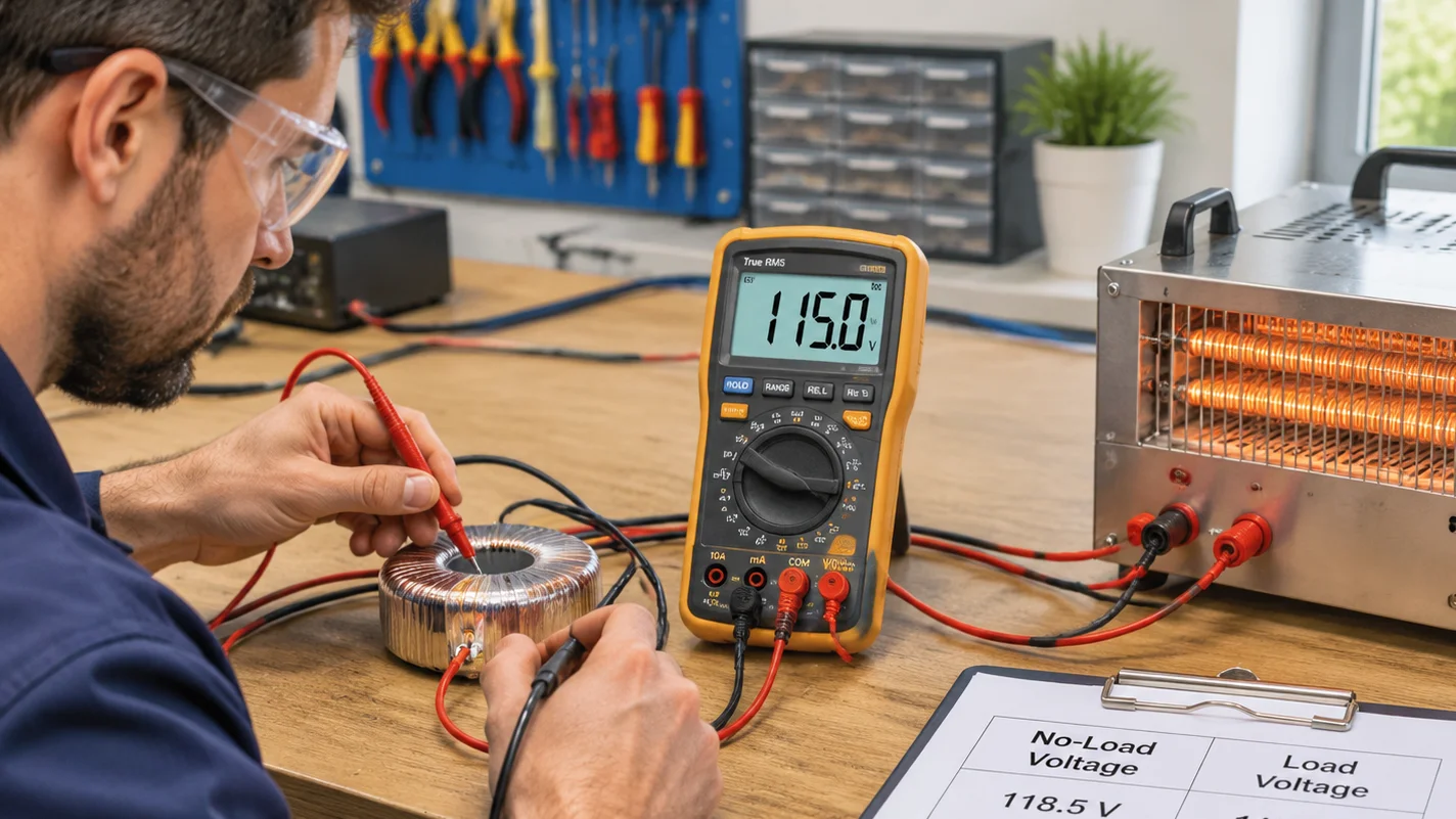
Without short-circuit data, measure it directly. Twenty minutes and two meters are enough.
Record the nameplate ratio and input tap, and measure primary voltage at the transformer terminals, not at the wall socket.
Energize with the secondary open and measure it on a true-RMS meter. Small toroidals routinely read 3–6% high here; that is normal.
Connect a resistive load bank at rated current — 17.4 A for 2 kVA at 115 V, roughly 2 kW of heaters.
Re-measure both voltages at the same moment. If the primary sagged, normalize the loaded reading by (Vprimary,no-load / Vprimary,loaded). Skipping this is the most common way to overstate regulation.
Repeat at operating temperature. Copper resistance rises about 0.4% per °C, so a cold reading flatters the transformer by 10–15% of its figure.
Separating transformer drop from cable drop
Measure at the transformer terminals and again at the load end. The difference is cable drop, and on a long 115 V run it is often larger than the transformer’s own contribution — a 20 m 2.5 mm² cable carrying 17 A loses over 5 V, more than the whole transformer. Oversizing does not fix a cable problem.
What Drives Regulation on a Small Transformer
العامل
Effect on regulation
Why
Conductor material
Aluminum 1.6× worse for the same volume
Higher resistivity raises per-unit resistance
Core geometry
Toroidal typically 20–40% better than EI
Shorter mean turn length, lower leakage flux — both r and x fall
Rated size
Worse below 500 VA
Terminations, leads and insulation take a larger share of the window
Wire gauge and fill
Sets r directly
Less copper means higher current density and more drop
Winding material deserves its own note: cost pressure toward aluminum is strong at this size, and the copper and aluminum winding trade-off shows up in regulation before it shows up anywhere else — invisibly, on a small unit’s nameplate.
How to Improve Voltage Regulation
Work down this list. The first two cost nothing and solve most complaints.
1. Set the input tap against the loaded voltage
This is the most common error in the field. A 230 V supply on a 220 V tap gives about 4.5% high output, confirmed by a no-load reading that looks perfect because regulation has not taken its cut yet. Set the tap so the loaded secondary lands mid-band — on a 110/120/220/240 V converter, the tap that looks right unloaded is usually one step too high.
2. Reduce the load fraction
Regulation scales almost linearly with load current in the first-order term, so running a 2 kVA transformer at 1 kVA roughly halves the drop. That is the real argument for buying one size up on cyclic loads — not efficiency, which barely moves.
3. Choose lower-impedance construction
Copper over aluminum, toroidal over laminated EI, and generous winding window fill all cut r and x directly. Check the capacity calculation method first; design quality matters more than the kVA label.
4. Fix the power factor deliberately
Capacitive correction reduces the q·x term and genuinely improves regulation — until it overshoots into leading power factor, where output rises under load and can exceed the no-load value. Add correction in steps and verify at light load, not only at peak.
5. Shorten and thicken the secondary run
Cable drop is not regulation, but the load cannot tell the difference. Move the transformer closer or increase conductor size before changing it.
6. Accept that passive regulation has a floor
If the incoming supply itself swings by 15%, no transformer can hold the output — the ratio is fixed. That is where an active device earns its cost, covered in voltage regulator vs stabilizer. A stabilizer corrects input variation; a transformer only minimises its own contribution.
Common Mistakes
خطأ
What it looks like
Correction
Setting the tap at no load
Output 4–6% high in service
Set the tap against the loaded reading
Blaming the transformer for cable drop
Voltage fine at terminals, low at the machine
Measure both ends
Comparing cold and hot readings
Regulation “improves” after a fix that changed nothing
Compare at the same winding temperature
Mixing denominator conventions
Two engineers, two answers, both “right”
State full-load or no-load base explicitly
Reading %Z as regulation
Predicted drop twice what the site shows
Apply power factor and load fraction
Expecting a bigger unit to fix a weak supply
New transformer, same sag
Measure the primary under load first
Below roughly 15 kVA, %Z is often not printed at all, so the calculation route is closed and only the bench method works. Knowing which nameplate fields are guaranteed saves arguing with suppliers.
الأسئلة الشائعة
What is a good voltage regulation percentage for a transformer?
For distribution work, 2–4% is good and 5% is acceptable. For small dry-type units under 5 kVA, 3–6% is normal and anything under 3% is well built. Sensitive electronics fed from a small transformer generally want 2% or better, which means oversizing.
Does a bigger transformer improve voltage regulation?
Yes, but mostly because the load fraction falls, not because large transformers are inherently stiffer. Halving the load fraction roughly halves the first-order drop. Below about 50% loading, further oversizing buys little and costs stand-by loss.
Why is my transformer’s output higher with no load?
That is regulation working as designed. With no current through winding resistance or leakage reactance, the secondary sits at the full turns-ratio value. Small toroidals also run 3–6% high unloaded so the loaded voltage lands on nominal.
Can voltage regulation be negative?
Yes. With leading power factor the capacitive current offsets the reactive drop and the secondary rises above its no-load value. In the 2 kVA example it goes negative below about 0.75 leading — relevant on supplies feeding power-factor-corrected switch-mode equipment.
How do I calculate regulation without short-circuit test data?
Measure it: no-load secondary voltage, then rated current into a resistive load with the primary at rated value. That is unity-power-factor regulation.
Where This Leaves You
Transformer voltage regulation is a small number with an outsized effect: a 4.5% drop on a 115 V rail puts you at 110 V, inside most equipment tolerances but outside the tighter ones. Calculate it from r and x if you have test data, measure it if you do not, and check the tap and the cable before blaming the transformer.
If you are specifying a converter for a fixed load and need the figure up front, tell us the load type, power factor and acceptable voltage band. The STU series toroidal step-up and step-down converters run from 100 VA to 5 kVA with selectable 110/120/220/240 V input taps, and toroidal construction is one reason regulation holds up at this size — send us the load details and we will confirm the right frame.
XFMR on electrical drawings simply means transformer — but the tag alone carries no ratings. Learn where it appears, which tags get confused with it, and the twelve fields that make it orderable.
The reduced-voltage starting method that gives the most torque per line amp: how the 50/65/80% taps work, how to wire and size a Korndorfer starter, and the five faults that show up at commissioning.
Percent impedance (%Z) on a transformer nameplate is the voltage needed to drive rated current through a shorted secondary. Here is what it means for 100 VA-10 kVA units.