Autotransformer Advantages and Limitations: When Not to Use One
Veröffentlicht: Autor: Lisa
Autotransformer advantages — smaller size, lower cost, higher efficiency — are real, but conditional. All of them come from one design fact: the input and output share part of the same winding, so only a fraction of the power is actually transformed. That fraction is set by the voltage ratio. Move the ratio away from unity, or add a requirement for isolation, and the advantages shrink or turn into liabilities.
This guide quantifies where those advantages hold, shows the ratio at which they stop paying for themselves, and lists five situations where an autotransformer should not be used at all. For wider product context, browse the step-up and step-down transformer range.
Where an Autotransformer Advantage Comes From
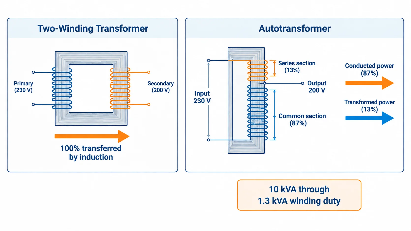
In a two-winding transformer, every watt crosses the core by induction, so both windings are built for the full throughput. In an autotransformer, the common winding carries only the difference between input and output current; the series portion is sized for the voltage difference.
Winding fraction = |1 − Vraus / Vin|
Take a 10 kVA unit stepping 230 V down to 200 V. Output current is 10,000 ÷ 200 = 50 A and input current is 10,000 ÷ 230 = 43.5 A. The common winding carries the 6.5 A difference at 200 V, the series winding carries 43.5 A across the 30 V difference. Both come to roughly 1.3 kVA of winding duty for 10 kVA of through power — about 13% of the copper and core a two-winding unit needs.
Conversion
Spannungsverhältnis
Winding fraction
Winding kVA for 10 kVA through
230 V → 200 V
1.15 : 1
13%
1.3 kVA
230 V → 190 V
1.21 : 1
17%
1.7 kVA
230 V → 115 V
2 : 1
50%
5.0 kVA
230 V → 100 V
2.3 : 1
57%
5.7 kVA
230 V → 76 V
3 : 1
67%
6.7 kVA
230 V → 46 V
5 : 1
80%
8.0 kVA
The Four Advantages, and the Condition Each One Needs
Lower material cost and weight
The saving tracks the winding fraction, which tracks how close the two voltages are. A 230 V to 200 V unit delivers the full benefit; a 230 V to 115 V unit delivers half of it.
Higher efficiency — under sustained load
Copper loss scales with winding duty, so a 13% winding fraction loses far less than a two-winding equivalent. Core loss does not scale down with the ratio, though, so at no load both designs draw a similar magnetizing current. On a load that runs a few minutes a day the gain is theoretical; on continuous duty it compounds — about 600 kWh a year on a 10 kVA unit with a 1.5-point advantage at 4,000 hours.
Tighter regulation — with a side effect
Tighter coupling and lower series impedance keep the output up from no load to full load. That same low impedance lets fault current climb, which is why the protection review below matters more here.
Compact, tappable, and adjustable
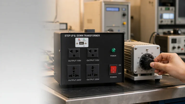
Taps on a shared winding are cheap to add, which is why the variable autotransformer became the default bench instrument for voltage testing — the TDGC2J variable transformer is a familiar example.
Vorteil
Physical reason
Condition for it to hold
Where it breaks down
Lower cost and weight
Only the series section is built for the voltage difference
Ratio below about 1.5 : 1
Above 2 : 1 the saving halves, then fades
Höhere Effizienz
Copper loss tracks the winding fraction, not throughput
Continuous or long-duty loading
Short intermittent duty, where no-load loss dominates
Better regulation
Lower series impedance, tighter coupling
Supply already has adequate fault protection
Weak supply or long cable runs
Adjustability
Cheap taps on a single winding
Adjustment only, isolation provided elsewhere
Any circuit that must float
Where the Advantages Stop Paying: The Ratio Ceiling
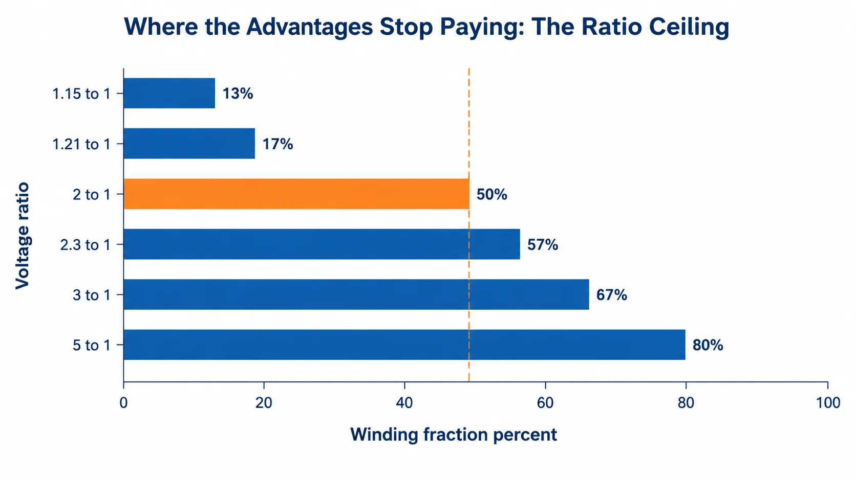
No switch flips at a particular ratio, but the trade stops making sense somewhere. At 2 : 1 you have given up half the material saving while still carrying the full isolation penalty. At 3 : 1 the winding is two-thirds of a full transformer, at 5 : 1 it is 80%. You pay nearly the full cost of a two-winding unit and get none of its separation.
Below 1.5 : 1 — usually the better choice, provided isolation is not required.
1.5 : 1 to 2 : 1 — quote both ways; size, weight, and panel space often decide it rather than price.
Above 2 : 1 — specify a two-winding transformer.
One further boundary matters: an autotransformer changes voltage only, never frequency. A 60 Hz unit asked to run a 50 Hz load will saturate, because flux rises with the voltage-to-frequency ratio — the mechanism behind transformer core saturation.
When Not to Use an Autotransformer: Five Hard Stops
1. The circuit must be galvanically isolated
This is the one that causes real damage. In a 230 V to 200 V unit the output sits on a tap 30 V below the top of the winding. If the series section fails open, the load is left connected to the full 230 V through the common winding; if the common section fails short, the output rises toward the input voltage. No second winding limits either event, and neither is visible at the output terminals. Where a standard or risk assessment calls for separation, the answer is an isolation transformer.
2. You need a neutral or a separately derived system
An autotransformer cannot create a neutral the supply does not have, nor establish a new grounded system. A three-wire supply cannot become a four-wire output, because the shared winding offers no independent point to bond. The bonding rules are covered in how to ground a transformer secondary.
3. Patient contact, wet locations, or portable equipment
These rely on the load side being isolated so a single fault cannot create a shock path. Medical equipment adds leakage-current limits a shared winding cannot meet, set out in medical-grade isolation transformers.
4. The load is harmonic-rich or transient-sensitive
Rectifier front ends, VFDs, and switch-mode supplies inject harmonics that the low-impedance shared winding passes rather than blocks. On three-phase units, triplen harmonics circulate through the common winding as heat.
5. The ratio is large, or the load must float
Beyond 2 : 1 the economics fail as shown above. A floating load — test benches, instrumentation front ends, anything that must not reference supply ground — fails on the same isolation point as item 1.
Situation
Why the autotransformer fails
Use instead
Isolation required by standard or risk assessment
Shared winding transfers faults and surges to the load
Two-winding isolation transformer
Neutral or separately derived system needed
No independent winding point to bond
Two-winding transformer with grounded secondary
Patient contact, wet area, portable tool
No separation, leakage current too high
Medical-grade isolation unit
Rectifier, VFD, or sensitive electronics
Low impedance passes harmonics and transients
Isolation transformer, add filtering if needed
Ratio above 2 : 1, or floating load
Saving gone, separation still absent
Two-winding step-up or step-down transformer
Four Sizing and Protection Traps
Nameplate kVA basis. Ask whether the rating is through-power or winding power. A 10 kVA winding rating on a close-ratio unit can pass far more than 10 kVA of load, so reading it the wrong way leaves you oversized or quietly overloaded.
Fault current. Lower impedance means higher available fault current at the load terminals than a two-winding unit of the same rating. Downstream breakers must be rated for the real value.
Neutral-ground bonding. Never create a second neutral-to-ground bond downstream — two bonds on one system put operating current on the grounding conductor.
Tap position. The winding fraction is valid only at the design tap, so a unit set elsewhere is no longer the same kVA rating and the protection settings no longer match.
A Ten-Minute Decision Sequence
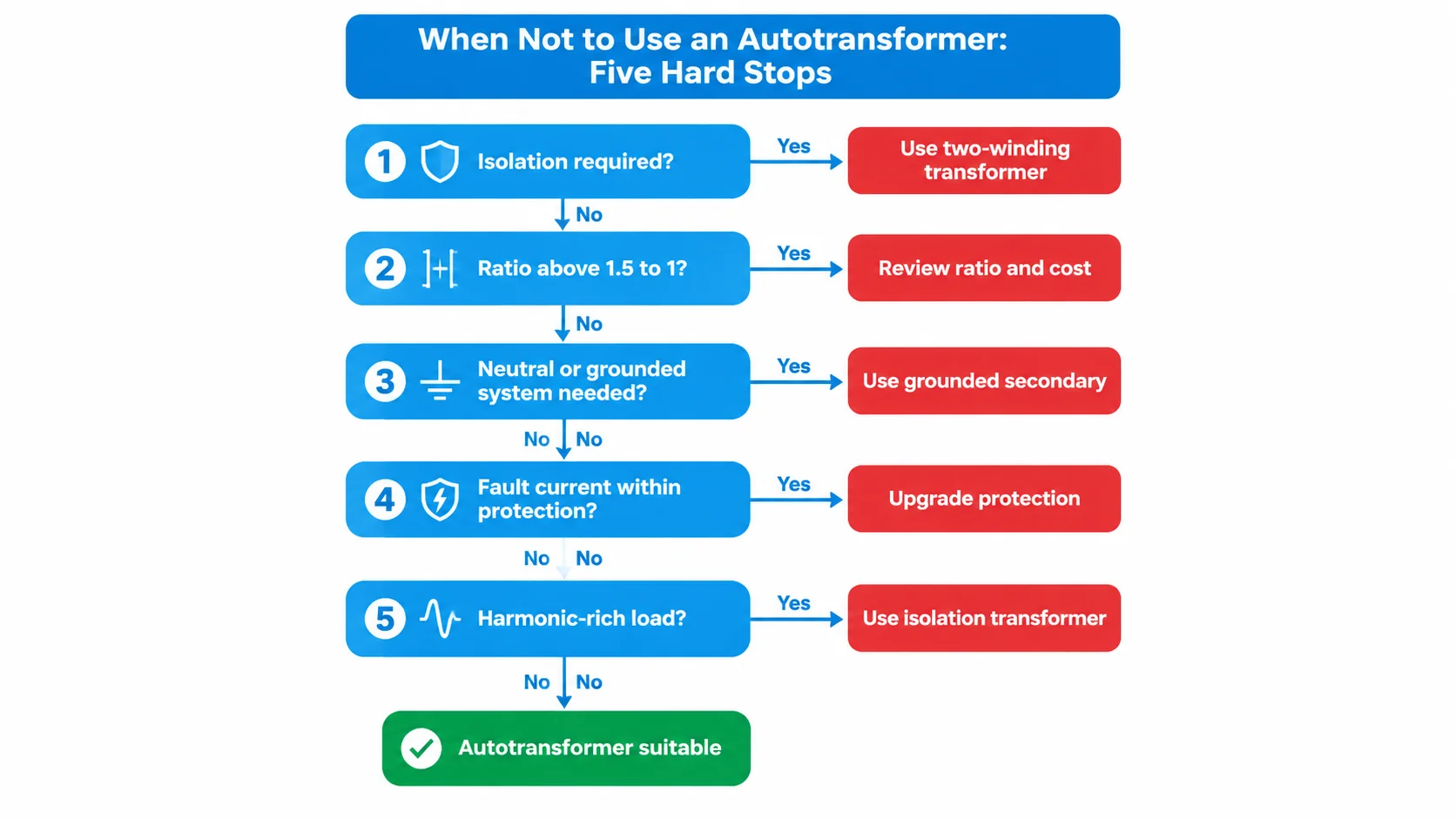
Does anything in the circuit require galvanic separation? If yes, stop — specify a two-winding transformer.
Is the voltage ratio inside 1.5 : 1? If not, compare landed cost, not unit price.
Does the load need a neutral or grounded reference the supply lacks? If yes, stop.
Is available fault current within the rating of the existing protection? If not, redesign the protection first.
Is the load harmonic-rich or transient-sensitive? If yes, isolation is doing real work here.
If all five checks pass, size the unit by through kVA and confirm the nameplate basis in writing.
When an Autotransformer Is the Right Choice
The advantages are genuine in the cases they were designed for: matching two systems that sit close in voltage, correcting a persistent 5% to 10% mismatch, reduced-voltage motor starting, and giving a test bench an adjustable supply. In each, the load either tolerates the shared reference or isolation exists upstream.
When the checks point to separation instead, the DT-10000VA toroidal step-up and step-down transformer is the two-winding alternative: separate primary and secondary, 110–120 V and 220–240 V windings, fuse and MCB protection on the input. It costs more and weighs more than an autotransformer of equal rating, and that difference is what you are buying.
Autotransformer advantages are a function of voltage ratio, not a fixed property of the product. Below 1.5 : 1, with no isolation requirement in the circuit, the shared winding gives you a smaller, cheaper, more efficient transformer. Above 2 : 1, or as soon as a neutral, a grounded system, or a floating load enters the picture, the same winding becomes the reason to choose something else. Confirm the kVA basis and the fault current in writing; those cause more field problems than the ratio.
FAQ
Do autotransformers provide electrical isolation?
No. The input and output share part of the same winding, so a conductive path exists between them. A fault on one side can reach the other, and the load cannot float relative to the supply.
When should you not use an autotransformer?
When isolation is required, when the load needs a neutral or a separately derived system, in patient-contact or wet locations, with harmonic-rich loads, or when the ratio exceeds about 2 : 1.
Can an autotransformer create a neutral?
No. A shared winding has no independent point to bring out as a neutral, so a three-wire supply cannot become a four-wire output. Use a two-winding unit with a grounded secondary.
Wie hoch ist das maximale Spannungsverhältnis bei einem Autotransformator?
There is no hard electrical limit, but the economics set a practical one. Above roughly 2 : 1 you pay most of a two-winding transformer’s cost with none of its separation.
Are autotransformers more efficient than isolation transformers?
Usually yes, because losses track the winding fraction rather than full throughput. The gap narrows at light load, where core loss is the same for both.
Can an autotransformer convert 230 V to 115 V?
It can, and the winding fraction at that ratio is 50%, so the material saving is half of what a 230 V to 200 V unit gives. If the load also needs isolation or a neutral, use a two-winding transformer.
A transformer cannot create cycles the supply does not have. What actually changes inside a 60Hz machine on 50Hz power, which loads genuinely do not care, and the three ways to convert frequency properly.
Gulf sites run 230/240V at 50Hz; imported US and Japanese equipment expects 110/120V at 60Hz. Sizing, wiring, ambient derating and the frequency limits of a step-down transformer, written for contractors and procurement teams.
A practical guide to variac testing: how engineers use a variable transformer for low-voltage bring-up, voltage-limit checks and burn-in tests, plus sizing, safety and common mistakes.