A transformer can double the voltage on its secondary and still deliver exactly the power it drew from the primary. That is not a design trick — it is bookkeeping enforced by physics. Power is conserved in transformers because there is no energy source inside the unit: it couples energy from winding to winding through a magnetic field, so whatever leaves the secondary comes out of the primary.
The honest version is less tidy. In an ideal transformer the balance is exact; in a real one the secondary delivers slightly less and the difference leaves as heat. The “98–99% efficient” figure repeated across the internet also describes utility-scale distribution units, not the 500 VA biến áp inside your control cabinet. Here is what power conservation does and does not guarantee, and how the gap shows up in sizing, cable cost, and the bill for a unit that sits energised all year.
The Short Answer: Voltage Rises, Current Falls by the Same Ratio
Two windings share one core, so the same changing flux links both and the volts per turn match on each side. That single fact produces the whole transformer identity:
Vp / Vs = Np / Ns = Is / Ip
Voltage and turns move together; current moves the opposite way. Multiply voltage by current on both sides and the ratio cancels, leaving VpIp = VsIs. That equality is the power conservation statement, and it applies to apparent power in volt-amperes, not only watts.
| Đơn đăng ký |
Cấp 1 |
Trung học |
Power both sides |
| Step-up, 240 V to 480 V |
4.17 A at 240 V |
2.08 A at 480 V |
1,000 VA |
| Step-down, 480 V to 240 V |
2.08 A at 480 V |
4.17 A at 240 V |
1,000 VA |
| Step-down, 230 V to 115 V |
2.17 A at 230 V |
4.35 A at 115 V |
500 VA |
It is also why a transformer cannot work on steady DC: constant flux induces no voltage.
What “Conserved” Means Once You Add Losses
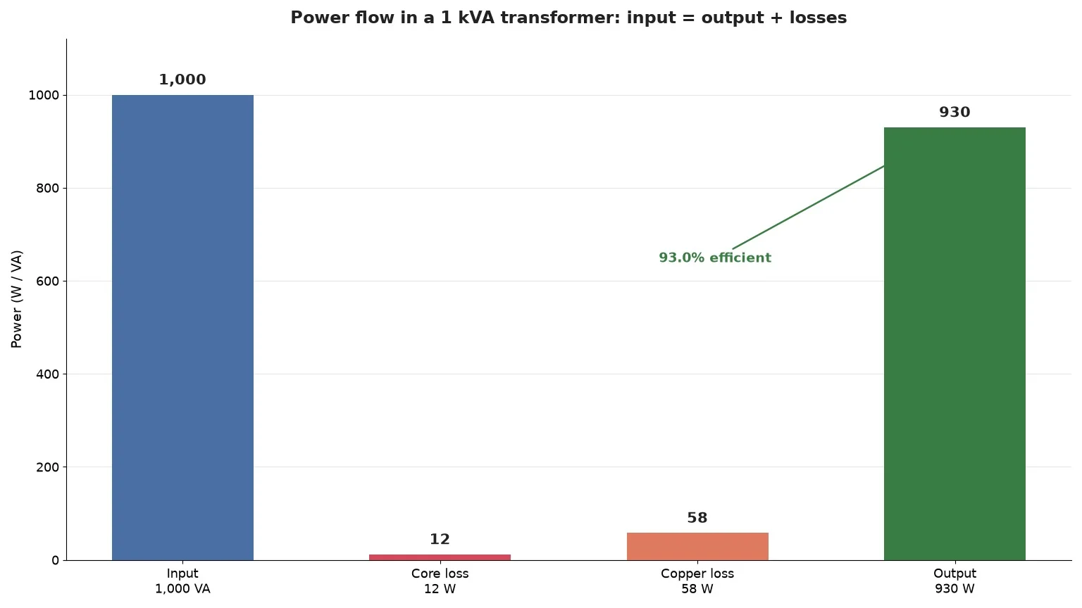
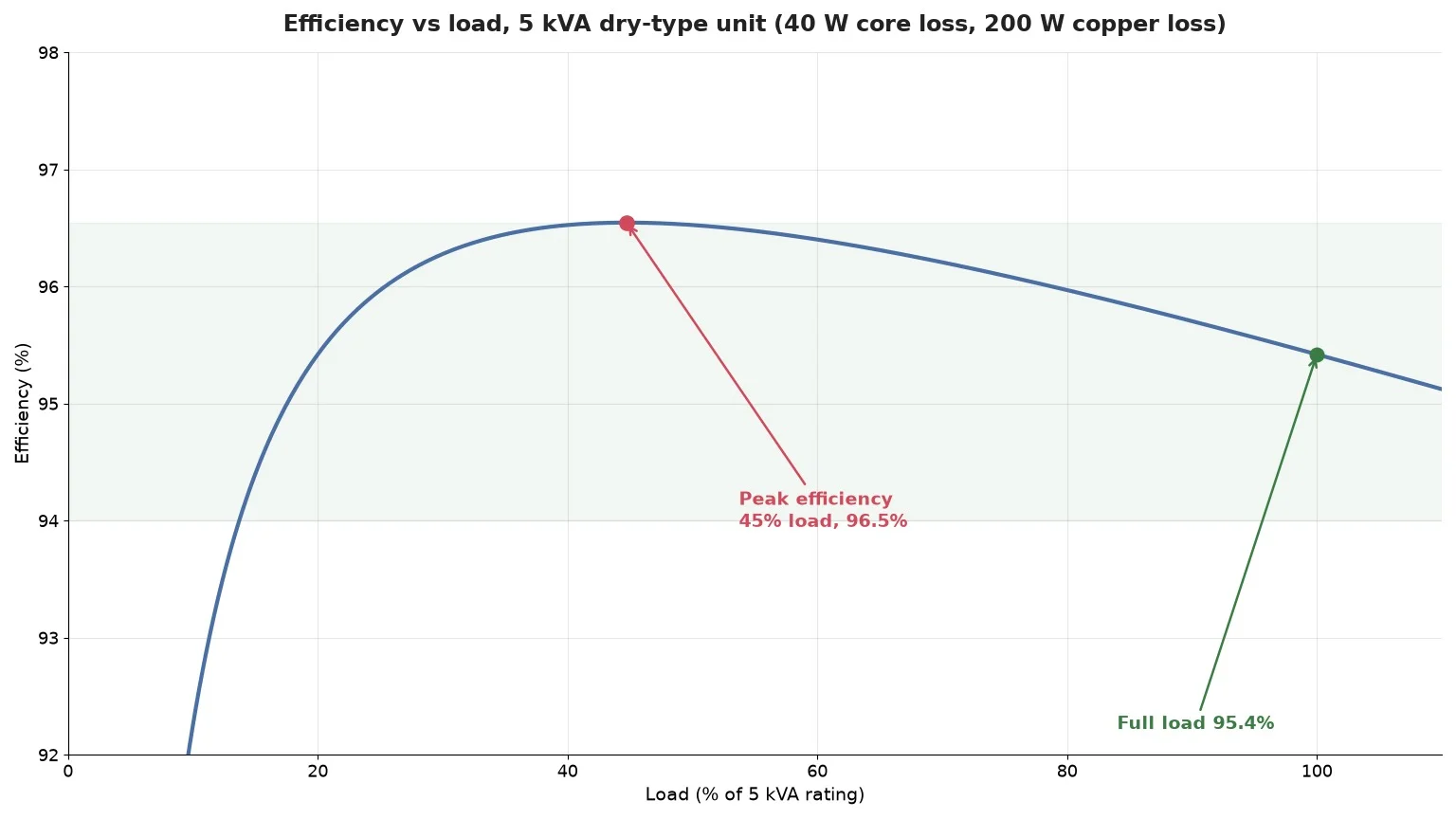
A real transformer obeys the same law with one extra term — input equals output plus the power converted to heat inside the unit. The two loss terms behave completely differently, and confusing them is the most common analytical mistake in small-transformer selection. Core loss is set by voltage and frequency, so it appears the moment the primary is energised, even with nothing connected. Copper loss is set by current, so it rises with the square of load.
| Loss |
Physical cause |
Scales with |
Present at no load |
| Hysteresis |
Core magnetic domains reversing each half cycle |
Frequency and flux density |
Đúng |
| Eddy current |
Circulating currents inside the laminations |
Flux density squared, lamination thickness squared |
Đúng |
| Copper (I²R) |
Resistance of the winding conductors |
Load current squared |
Không |
| Stray and leakage |
Flux missing the other winding, eddy currents in the frame |
Load and geometry |
Partly |
Efficiency combines them into one number, with the copper term scaled by the square of the load fraction. Because core loss is flat and copper loss is quadratic, the curves cross below full load — and that crossing is where efficiency peaks, typically between 45% and 75% of rating. Continuous operation at 100% load is therefore the thermal limit rather than the efficiency optimum. Winding resistance itself is a material decision, covered in copper versus aluminum windings.
Three Things Power Conservation Does Not Give You
Impedance is not conserved — it scales by the square of the ratio
A load on the secondary is not seen at face value from the primary; it is reflected through the square of the turns ratio, so a 4 Ω load behind a 2:1 step-up looks like 1 Ω to the source. That falls straight out of VpIp = VsIs plus Ohm’s law, and it is why a transformer changes the fault current a downstream breaker must interrupt — see percent impedance explained.
Power factor belongs to the load, not the transformer
The transformer conserves kilovolt-amperes; it does not decide how many of them do useful work. A 5 kVA unit feeding a load at 0.6 power factor delivers 3 kW, and the remaining 2 kVAR circulates between load and source through the windings, heating them every cycle. Sizing on kW instead of kVA undersizes the unit every time.
Voltage regulation is never zero
The turns ratio sets the no-load voltage ratio. Under load, winding impedance drops a few percent, so the secondary sags while the power balance still holds. A unit reading 240 V open-circuit may sit at 232 V at full resistive load. Conservation of power and constancy of voltage are separate promises, and only the first is guaranteed — the arithmetic is in transformer voltage regulation.
Why Power Conservation Is the Reason Grids Run at High Voltage
This is where the physics turns into money. Line loss goes as I²R and power goes as VI, so conserving power while raising voltage cuts current by the same factor and cuts loss by the square of it.
| Delivery voltage |
Current for 100 kW |
Loss in a 0.5 Ω line |
| 240 V |
417 A |
87 kW — impossible |
| 4,800 V |
20.8 A |
217 W |
| 13,800 V |
7.2 A |
26 W |
At 240 V the loss exceeds the load, which is the whole argument for transmission at hundreds of kilovolts. The same arithmetic applies at cabinet scale: a 2 kVA load 60 m from its source needs far heavier conductors at 240 V than at 480 V with a local step-down, often dearer than the transformer itself. Put the transformation where the copper is cheapest.

The Efficiency Figure That Does Not Apply to Your Unit
Search for transformer efficiency and you will find 97% to 99% everywhere. Those numbers come from distribution transformers rated 15 kVA and up, where core and winding mass is large relative to the load. Shrink the unit and the surface-to-volume ratio works against you: the same fractional loss has less material to spread through, and fixed costs such as lead wire and terminals do not shrink proportionally.
| Rating |
Typical full-load efficiency |
Typical no-load loss |
| 100 VA |
82–90% |
2–4 W |
| 500 VA |
88–93% |
5–9 W |
| 1 kVA |
90–94% |
9–14 W |
| 3 kVA |
93–96% |
20–30 W |
| 5 kVA |
94–96% |
30–45 W |
| 15 kVA dry-type |
96–98% |
60–110 W |
| 100 kVA and above |
98–99% |
300 W and up |
Treat these as design-typical ranges, not guarantees: lamination grade, conductor material, insulation class, and allowable temperature rise all shift the result, and a unit’s test report overrides any table. What the ranges do tell you is that a 100 VA unit can lose one watt in six, and that planning a 500 VA load on a 500 VA transformer leaves no margin for losses.
Sizing and Operating Cost: Where Conservation Sends the Bill
Sizing follows from the balance: required primary capacity is load in kVA divided by efficiency. A 3.5 kVA load on a unit running 94% efficient needs 3.72 kVA, so the next standard size is 5 kVA, not 3.5 kVA. Skip that step and the unit runs above its thermal rating, shortening insulation life long before outright failure — the early symptoms are in Các dấu hiệu cảnh báo máy biến áp quá nhiệt.
No-load loss is the part buyers forget, because it is invisible on a load survey. A 5 kVA unit with 35 W of core loss, energised for 8,760 hours, burns about 307 kWh a year doing nothing — roughly USD 37 per unit, or USD 370 for ten in one panel before a single load is switched on. For equipment that idles most of the time, core loss rather than full-load efficiency is the figure worth asking about.
Ambient conditions move the same needle: a unit rated for a 40 °C rise in free air runs hotter inside a sealed enclosure and must be derated. Frequency matters too, since core loss and flux density both depend on it — see 50 Hz versus 60 Hz operation và core saturation.
Three Cases That Look Like a Violation
Inrush current. Switching on can draw 8 to 12 times rated current for a few cycles while the core field establishes itself. Nothing is created: energy is borrowed from the source to build the field and returned as it collapses. The secondary delivers nothing during that window, so the primary spike has no matching output.
Non-linear loads. Rectifiers and switch-mode supplies draw current in pulses, and those harmonics add eddy loss in the windings and stray loss in the frame. The kVA balance still holds; the heat does not scale with it.
DC offset and half-cycle saturation. A DC component pushes the core toward saturation on one half cycle, so primary current spikes while output power barely moves. Conservation is intact — the excess is magnetising current, not transferred power — but protective devices see an overload that is not there.
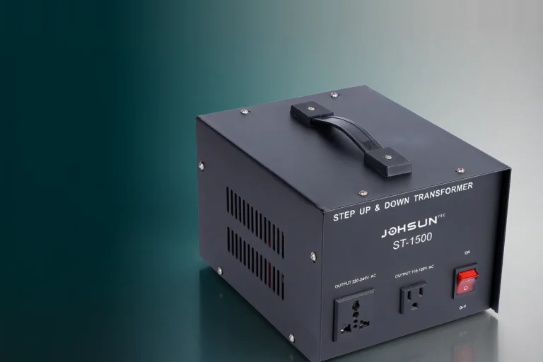
Units from 100 VA to 5 kVA sit right where these effects matter, because there is little thermal mass to absorb them. If you are sizing one for a control panel or test bench, the STU series step-up and step-down transformers publish their ratings and temperature rise, so the arithmetic above can be checked against a real datasheet.
Các câu hỏi thường gặp
Is power conserved in a real transformer?
Nearly. Output equals input minus losses, which for small dry-type units run from roughly 4% to 15% of throughput. Energy conservation is not broken — the losses are part of the balance and leave as heat.
Why does a step-up transformer raise voltage without raising power?
The magnetic field transfers energy rather than creating it. More secondary turns raise volts per turn proportionally and lower available current by the same factor, so the volt-ampere product stays fixed.
Can a transformer deliver more than its kVA rating?
Briefly, yes — the rating is a thermal limit, not a hard electrical ceiling. Sustained overload raises winding temperature, accelerates insulation ageing, and shortens life.
What is the difference between kVA and kW in a transformer?
kVA is apparent power, which is what the transformer must carry and dissipate. kW is real power, set by the load’s power factor. A 5 kVA unit at 0.8 power factor delivers 4 kW; the other 3 kVAR still flows through the windings and produces heat.
Does a transformer waste power when nothing is connected?
Yes. Core loss is present whenever the primary is energised, because the core is magnetised and demagnetised 50 or 60 times a second — typically 30 to 45 W on a 5 kVA unit, around the clock.
Bài học thực tiễn
Power conservation in a transformer is a statement about energy transfer, not a promise of perfect efficiency or constant voltage. Voltage and current trade places in inverse proportion, the volt-ampere product crosses the unit almost intact, and the shortfall appears as heat you pay for twice — in the losses, and in the derating margin they force. Size on kVA, divide by efficiency before choosing a standard rating, and ask for the no-load loss figure if the unit runs around the clock.
If you want loss and temperature figures for a candidate unit rather than a range, send us the load details — voltage ratio, load type, duty cycle, and ambient — and we will match a rating to it.