230V to 110V Transformer for Spain: REBT and Secondary Earthing
230V to 110V transformer for Spain: REBT compliance, ITC-BT-18 and ITC-BT-24, earthing the secondary and UNE-EN IEC 61558 documentation.
Read More
 English
A step down voltage converter reduces a higher electrical supply voltage to a lower usable voltage. A PWM-to-voltage converter does something different: it turns the duty cycle of a pulse-width-modulated signal into a proportional analog voltage, usually for measurement or control. The first handles power for a load; the second usually handles a low-power signal.
The names sound similar because both can produce a lower average voltage. However, they differ in purpose, output waveform, regulation, current capacity, isolation, and safety. A PWM signal that alternates between 0V and 12V at 50% duty cycle has a 6V average, but it is still a train of 12V pulses. It is not automatically equivalent to a regulated 6V supply.
| Feature | Step down voltage converter | PWM voltage converter |
|---|---|---|
| Primary purpose | Deliver lower-voltage power to a load | Recover an analog level from PWM duty cycle |
| Typical input | AC mains or DC power source | Logic-level PWM pulse train |
| Typical output | Lower AC or regulated lower DC voltage | Low-power analog signal |
| Main components | Transformer, or switches with inductor and capacitors | RC low-pass filter, sometimes an op-amp buffer |
| Load capability | Specified in VA, watts, or output current | Usually intended for a high-impedance input |
| Feedback regulation | Common in electronic DC converters | Usually not power-supply regulation |
| Typical use | Appliances, controls, electronics, industrial equipment | Microcontroller output, sensor decoding, analog commands |
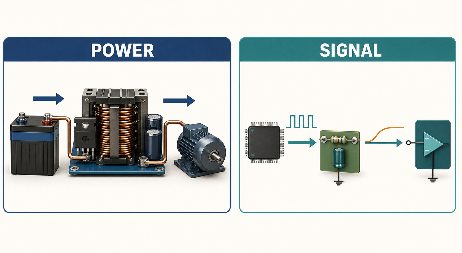
A step down voltage converter takes a higher input voltage and supplies a lower output voltage. The term covers two important product families: AC-to-AC transformer converters and DC-to-DC buck converters.
For international appliances, a step-down transformer commonly converts 220–240V AC to 110–120V AC. It uses magnetic coupling between windings, and its turns ratio determines the approximate voltage ratio. Models may be rated from a few hundred VA to several kVA. Browse the step-up and step-down transformer category for examples across different capacities.
A transformer changes the nominal AC voltage but normally does not change the supply frequency. A 60Hz-only motor or timer may therefore remain incompatible with a 50Hz supply even when the voltage is correct. Autotransformer designs also do not provide galvanic isolation unless the product specifically includes an isolation transformer.
A buck converter reduces one DC voltage to a lower regulated DC voltage. A switching transistor rapidly connects and disconnects the input, while an inductor and capacitor store and smooth energy. A feedback loop adjusts the switching duty cycle to hold the output near its setpoint as input voltage and load current change.
PWM is therefore often used inside a buck converter, but the complete converter is more than a PWM generator. It includes a power stage, energy-storage components, a control loop, protection, and output filtering. That distinction explains why a bare PWM output cannot usually replace a DC power supply.
A PWM-to-voltage converter translates duty cycle into an average analog level. If a PWM waveform switches between 0V and a high level of VH, its ideal average is approximately:
VOUT = duty cycle × VH
For example, a 3.3V PWM signal at 25% duty cycle corresponds ideally to about 0.825V after averaging. A resistor-capacitor low-pass filter can attenuate the switching carrier and leave a slowly changing analog level. An op-amp buffer may be added when the next circuit needs a low output impedance or a different voltage range.

The RC time constant creates a tradeoff. More filtering reduces output ripple but slows the response when duty cycle changes. Less filtering responds faster but leaves more ripple. PWM frequency, desired settling time, allowable error, filter order, component tolerance, and the load impedance all influence the result.
The output also depends on the actual PWM high and low levels. Supply variation, driver resistance, cable interference, and input loading can affect accuracy. For precision control, a dedicated digital-to-analog converter may provide better linearity, settling behavior, and repeatability.
Suppose a controller produces 24V pulses at 50% duty cycle. A meter may display an average near 12V, but the connected circuit still sees 24V during every on-time. A load designed for a maximum of 12V may be damaged by the pulse amplitude even when the mathematical average looks correct.
Some loads naturally average PWM energy. A brushed DC motor’s inductance and mechanical inertia, for example, can make PWM useful for speed control. LEDs can be dimmed with an appropriate current-control circuit. Sensitive electronics, sensors, communications devices, and circuits expecting clean DC may instead reset, overheat, produce noise, or fail.
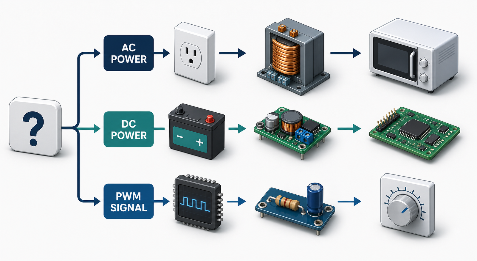
If you need to operate an appliance or electronic assembly, you are moving power and need a properly rated converter. If you need to communicate a setpoint from a microcontroller to an analog input, PWM-to-voltage conversion may be appropriate.
For 230V-to-115V appliances, use an AC step-down transformer designed for the local mains. For 24V DC to 12V DC electronics, use a buck converter. For a 3.3V logic PWM signal that must become a 0–3.3V analog command, use a low-pass filter or DAC architecture.
Read the appliance nameplate and compare its voltage, watts, current, and frequency with the converter specifications. For transformer products, VA is important. Motors, compressors, pumps, and transformers may draw several times their normal current at startup, so a converter needs sufficient surge headroom.
Lower-power appliances may fit an ST-1500VA 220V-to-110V converter or an ST-2000VA step-down transformer. Larger loads can be compared against the ST-3000VA voltage converter and ST-5000VA step-down transformer. Final selection should always use the detailed product specification and the actual load profile.
Specify the PWM frequency, logic levels, duty-cycle range, acceptable ripple, settling time, load impedance, and required output range. A single RC filter may suit a slow noncritical command. A buffered multi-pole filter or dedicated DAC is usually better when fast response and low ripple are both important.
Power converters should have appropriate overload, short-circuit, overtemperature, grounding, fuse or breaker, and ventilation provisions. Mains-voltage work must follow the product instructions and applicable electrical requirements. For branded panels, socket formats, voltage ranges, packaging, or project-specific specifications, review Johsun Tec’s ODM and OEM options.
A step down voltage converter is the correct choice when a load needs lower-voltage power. A PWM voltage converter is the correct choice when a PWM duty cycle must become an analog signal. Although a buck converter often uses PWM internally, it adds the energy storage, filtering, feedback, and protection required for controlled power delivery.
Learn more about the manufacturer on the Johsun Tec home page and About Us. For help matching an AC step-down converter to your supply voltage, equipment rating, startup demand, and operating conditions, contact Johsun Tec.
Not by itself. A PWM controller creates timed pulses. It can control the power switch inside a buck converter, but a complete voltage converter also needs a suitable power stage, filtering, feedback, and protection.
It can turn PWM into a smoothed analog signal for a high-impedance input. The result has ripple and a finite response time, and it is generally not intended to power an appliance or other high-current load.
It means the ideal average is halfway between the low and high PWM levels. The instantaneous waveform still reaches the full high level during each pulse.
Yes, when it is designed for those nominal voltages and sized for the connected load. Confirm frequency compatibility, VA capacity, plug and socket format, grounding, and duty rating.
Use a buck converter to supply regulated lower-voltage DC power. Use a PWM filter when a low-power analog signal must represent PWM duty cycle. If both power conversion and analog control are needed, they may exist as separate stages.