Why “Check the Temperature” Is Not a Maintenance Plan
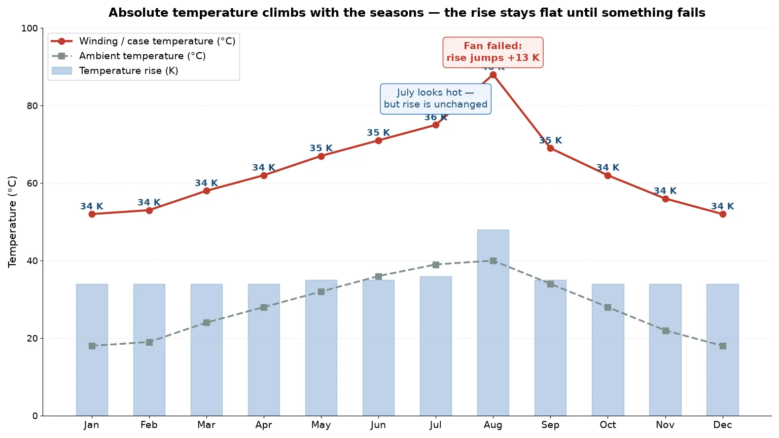
Almost every power transformer maintenance schedule says the same thing: check the temperature. Very few say what to do with the number. A winding reading of 68 °C is comfortable in February and worrying in August, because the transformer does not care how hot it is in absolute terms. It cares how far that temperature sits above the air around it. That gap — the temperature rise — is the only figure that stays comparable across the year, and it is the one worth writing down.
This guide treats power transformer maintenance as a thermal-margin discipline rather than a checklist. You will see what each reading actually measures, how ambient temperature quietly resets your usable kVA, what temperature monitoring should look like in each season, and which drift thresholds justify an investigation.
What Temperature Monitoring Really Measures
Four temperatures exist on any transformer, and they are not interchangeable. Mixing them up is the most common reason a monitoring program produces confident, wrong conclusions.
- Ambient — the air entering the unit, measured in shade, one to two metres away, outside the exhaust plume.
- Top-oil — on oil-immersed units, read from the dial thermometer in the tank top.
- Case or surface — on dry-type and small sealed units, the only direct reading available without embedded sensors.
- Winding — average winding and hot-spot temperature, which is what actually ages insulation. Below a few hundred kVA the hot spot is calculated, not measured.
The relationships matter more than the definitions. On an oil-immersed unit the winding hot spot runs 10–20 K above top oil at rated load. On a small dry-type unit the winding sits well above the case, and the case is a lagging, averaged proxy — useful precisely because it is stable at steady load.
All nameplate ratings are defined against a reference ambient, usually 40 °C maximum for IEC designs. That is why nameplate kVA is not a constant: it is a value valid at one air temperature.
Temperature Rise Is the Number You Should Log
Temperature rise is measured temperature minus ambient at the same moment. Log the subtraction and the seasonal noise disappears.
| Reading |
Ambient |
Winding or case |
Rise |
Interpretation |
| January, full load |
18 °C |
52 °C |
34 K |
Baseline |
| April, full load |
26 °C |
60 °C |
34 K |
Unchanged — unit is healthy |
| July, full load |
39 °C |
74 °C |
35 K |
Unchanged — hot weather, not a hot transformer |
| August, after fan failure |
40 °C |
88 °C |
48 K |
+13 K drift — investigate |
Between January and July the absolute reading climbed 22 K while the rise moved by one. Anyone logging only temperature would have opened a work order in July and missed the real fault in August. A rise that drifts more than about 10 K at the same load and the same measurement position is a genuine signal; a rise that stays flat while the reading climbs is weather.
This is also why the rated rise on the nameplate deserves a second look. A dry-type unit marked Class F with a 100 K rise is designed for roughly 140 °C average winding temperature at 40 °C ambient, leaving about 15 K of hot-spot headroom inside the 155 °C limit. That arithmetic, not the class letter alone, is what your thresholds should be built on.
How Ambient Temperature Resets Your Usable kVA
Temperature rise scales with total losses and load loss scales with current squared, so available load follows a square-root relationship with the rise still available. For a Class F dry-type rated 100 K at 40 °C:
| Ambient |
Available rise |
Usable share of nameplate kVA |
| 20 °C |
120 K |
110% |
| 30 °C |
110 K |
105% |
| 40 °C (rated) |
100 K |
100% |
| 45 °C |
95 K |
97% |
| 50 °C |
90 K |
95% |
| 55 °C |
85 K |
92% |
Two conclusions pull in opposite directions. A 100 K rise machine is only mildly sensitive to ambient swing — a 15 K hotter day costs about 8% of capacity, not 30%. But that insensitivity also means you cannot buy much headroom back in winter. A large seasonal capacity swing is a sizing decision at purchase, not an operating trick.
The widely quoted “derate 8% per 10 °C above 40 °C” shortcut is more aggressive than the square-root result because it assumes rise scales linearly with load. Use the square-root figure and treat the shortcut as a conservative screen; the derivation is in our guide to choosing a transformer insulation class.
A Seasonal Regime That Fits a Real Site
Seasonal maintenance fails when it is written as tasks without a measurement attached. Each season below has one primary threat, one measurement that detects it, and one trigger that changes what you do.
Before the hot season: the baseline week
The most valuable action of the year is a controlled baseline taken before ambient climbs. Run the unit at a steady 60–80% of nameplate for at least two hours, then record ambient, case or top-oil, and current per phase. Every later reading is compared against this one; without it you can detect a catastrophe but not a slow decline. In the same visit, clear dust and pollen from vents and fins, confirm nothing is stacked within a metre of the intake, verify the fan moves air at the outlet rather than merely spinning, and torque the terminal lugs. Loose terminations are the most common cause of a hot spot that appears only in summer.
Peak summer: hours above threshold, not average temperature
Insulation aging is cumulative and roughly doubles for every 6–8 K of sustained extra hot-spot temperature. A unit that spends six hours a day at 110% load ages far faster than one that touches 130% for twenty minutes. Record duration above threshold, not just the peak, and where load is discretionary — process scheduling, charging, HVAC staging — shift it out of the afternoon block instead of adding cooling.
Wet season and autumn: the insulation side
Once ambient falls, thermal risk drops and moisture risk rises. Condensation shows up first as falling insulation resistance, not as heat, so this is the season to measure rather than watch temperature. Autumn also brings airborne debris into intakes that were clear in June, and outages are cheapest to schedule then. Do the cleaning and insulation check now, not in the week before the next hot season.
Winter: two risks that are not overheating
Cold ambient gives thermal headroom, which tempts people to call winter the safe season. Two failure modes disagree. Cold-start condensation: a unit soaked at −5 °C and energised inside a warm humid room condenses moisture directly onto windings. Grid over-voltage: lightly loaded winter networks run at the top of their tolerance band, and a transformer at 108% of rated voltage draws more magnetising current and runs a hotter core even at low load. If winter case temperature rises while load falls, suspect excitation rather than load — the mechanism is described in our article on transformer no-load losses.
| Season |
Primary threat |
Measurement |
Trigger for action |
| Pre-summer |
Connection resistance, blocked airflow |
Baseline rise at known load; infrared scan |
Any terminal more than 10 K above its peers |
| Peak summer |
Sustained overload, fan degradation |
Rise plus hours above threshold |
Rise drift above 10 K, or over 4 h/day at 110% |
| Wet season / autumn |
Moisture ingress, blocked intakes |
Insulation resistance, outlet airflow |
Insulation resistance falling versus last season |
| Winter |
Cold-start condensation, over-excitation |
Supply voltage, case temperature at low load |
Case temperature rising while load falls |
Monitoring a Transformer That Has No Sensors
Most units between 100 VA and 10 kVA ship without a thermometer, RTD, or communications port. They can still be monitored — just from outside.
Infrared scanning, done properly
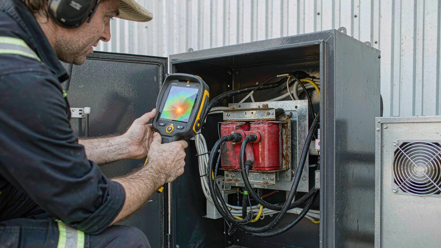
An infrared scan is only meaningful under load. Rise is dominated by load loss, so at 20% load a failing connection can look perfect; scan at 40% load or more and compare like with like — phase to phase, same time of day. Set emissivity near 0.95 for painted enclosures, but note that shiny bare copper and aluminium sit far lower, and an uncorrected reading on bright metal can be wrong by tens of kelvin. Do not scan through glass, in direct sun, or in a draught.
The resistance method for winding temperature
Where you need real winding temperature rather than a surface proxy, measure winding resistance cold, run to thermal steady state, then measure again and convert. For copper windings, T2 = (R2 / R1) × (234.5 + T1) − 234.5. It is the same arithmetic used in acceptance testing, and it turns an ordinary multimeter into a winding thermometer.
A controlled heat test on the bench
For small dry-type units, the cleanest baseline comes from a stepped test at reduced voltage: raise the applied voltage in small increments and let the case settle at each step. A variable transformer makes that repeatable, because you can hold an exact input and reproduce it next season. The TDGC2J series 0.5–5 kVA variable transformer is the type of unit used for this bench work — a test instrument here, not a substitute for the transformer under test.
Reading the Trend: What Each Drift Pattern Means
With a baseline in place, most diagnoses reduce to pattern matching.
| Observation at steady load |
Likely cause |
Next check |
| Rise up 5–10 K, gradual |
Dust-blocked vents, fan wear, hotter enclosure |
Clean, verify outlet airflow, re-measure at same load |
| Rise up over 10 K, abrupt |
Connection resistance, winding fault, real overload |
Infrared scan, phase balance, DC resistance |
| One terminal 10–15 K above its peers |
Loose lug or oxidised contact |
Re-torque to specification, re-scan under load |
| Normal at light load, high at full load |
Load-loss problem, not core loss |
Winding and connection resistance |
| High even at no load |
Over-excitation, supply voltage high |
Log supply voltage across the day |
| Case hot, terminals cool, load low |
Restricted convection or over-voltage |
Clearance around unit, voltage record |
None of these patterns needs a specialist to spot, and all of them need a baseline to exist. That is the whole argument for logging rise instead of temperature.
Five Monitoring Mistakes That Cost Transformers
- Comparing absolute temperatures across seasons. July always looks worse than January. It usually is not.
- Taking ambient beside the hot case. A sensor on the enclosure, in the exhaust stream, or in sunlight reads 10–15 K high and hides a real increase.
- Scanning at light load. Everything looks healthy when load loss is a few percent of rating.
- Trusting a fan because it spins. A blocked intake still produces rotation. Verify airflow at the outlet.
- Assuming winter is safe. Condensation and over-excitation both appear in cold weather, and neither shows up if nobody is looking.
A One-Page Seasonal Log
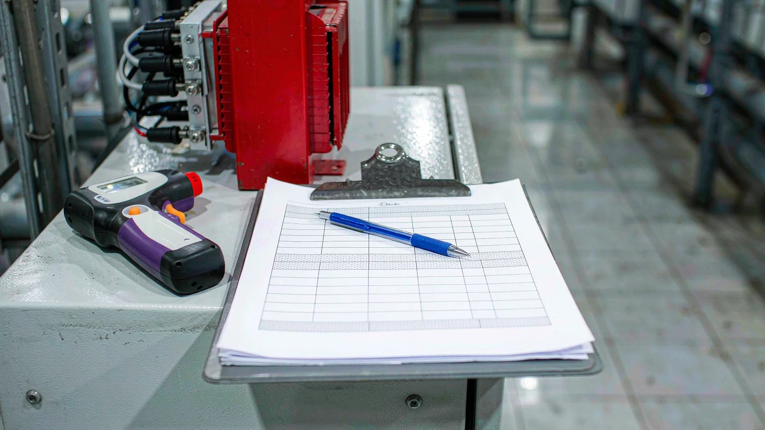
Format matters less than consistency: every reading at a similar load band and the same physical position, or the comparison is worthless.
| Date |
Load (A per phase) |
Ambient |
Winding or case |
Rise |
Drift |
Hours above threshold |
Action |
| 15 Jan |
21.4 / 21.8 / 21.1 |
18 °C |
52 °C |
34 K |
— |
0 |
Baseline set |
| 12 Apr |
21.6 / 21.9 / 21.2 |
26 °C |
60 °C |
34 K |
0 K |
0 |
None |
| 08 Aug |
22.0 / 22.4 / 21.9 |
40 °C |
88 °C |
48 K |
+14 K |
5.5 |
Fan inspected, intake cleared |
What to Do Next
Seasonal maintenance is not a longer checklist; it is a smaller one aimed at the right variable. Set one baseline rise per unit before the hot season, log rise rather than temperature, watch duration above threshold as closely as the peak, and let drift — not absolute value — decide when to investigate.
If you are sizing a replacement or an additional unit for a site with a wide ambient swing, or need a controlled source for a bench heat test, tell us the ambient range, load profile and duty cycle and we will recommend a configuration rather than a catalogue number.
FAQ
What temperature should a power transformer run at?
There is no single answer, because the limit is set by insulation class and by rise, not by the absolute reading. A Class F dry-type is typically designed for 100 K rise at 40 °C ambient, putting average winding near 140 °C and the hot spot near the 155 °C limit. A case reading of 70 °C can be normal in a 40 °C room and abnormal in a 20 °C room.
How often should transformer temperature be monitored?
Continuously if the unit has sensors. Otherwise weekly at peak load during the hot season, monthly in shoulder months, and once before the hot season as a formal baseline. Frequency matters less than consistency — readings at different loads cannot be compared.
Is it normal for a transformer to be hotter in summer?
Yes, provided the rise stays flat. If ambient rises 15 K and the winding rises with it, the unit is behaving exactly as designed. Only a change in the difference indicates a problem with the transformer itself.
Can I run a transformer at full load in 50 °C ambient?
On a 100 K rise design, about 95% of nameplate is the thermally equivalent load at 50 °C. Running at 100% is not instantly destructive, but it consumes insulation life faster, and the effect compounds across a season of hot days.
What is the difference between top-oil and winding temperature?
Top-oil temperature is measured in the tank and responds slowly. Winding hot-spot temperature is the hottest point inside the winding and runs 10–20 K above top oil at rated load on an oil-immersed unit. Insulation ages at the hot spot, so top oil is an indicator rather than the limit.
Does cold weather damage transformers?
Not through overheating, but through condensation when a cold unit is energised in a warm humid space, through over-voltage on lightly loaded winter networks, and through mechanical stress on brittle insulation. A winter inspection should focus on insulation resistance and supply voltage, not temperature.