Every transformer has a rating on its nameplate, usually in VA or kVA. That number is not a suggestion — it is the maximum continuous load the windings can carry before heat starts to damage the insulation. When connected equipment asks for more than the rating, the transformer is overloaded. Knowing how to calculate the overload of a transformer lets you catch an unsafe condition before it becomes a burned winding, a tripped breaker, or a failed machine. This guide covers the formulas, a step-by-step load check, and the Transformator sizing rules that keep equipment safe.
What Does Transformer Overload Mean?
Transformer overload simply means that the actual load on the secondary side exceeds the rated capacity of the unit. The nameplate rating — for example 1000 VA, 3 kVA, or 500 kVA — is the apparent power the transformer can supply continuously without exceeding its designed temperature rise.
Overload is a heat problem before it is an electrical problem. Copper loss in the windings rises with the square of the current, so a modest current increase produces a much larger temperature increase. Sustained over-temperature accelerates insulation aging, shortens service life, and can eventually cause failure or fire.
Why Calculating Load Before Connecting Matters
Most overload-related failures are preventable. The check takes five minutes with a calculator, yet skipping it is one of the most common mistakes made by maintenance teams and buyers:
- It prevents downtime. An overloaded transformer usually fails at the worst moment — during peak production.
- It protects connected equipment. A heavily loaded transformer regulates voltage poorly, so sensitive machinery sees dips and brownouts.
- It avoids wasted money. Buying far larger than the load wastes budget, while a slightly undersized unit forces an emergency replacement.
The Basics First: VA, kW, and Power Factor
Before using the formulas, understand why transformers are rated in VA or kVA rather than watts. A transformer supplies both working power (kW), which does useful work, and reactive power (kVAR), which sustains magnetic fields in motors and other inductive loads. Together they form apparent power (kVA) — the quantity the windings must physically carry. That is why transformers are rated in kVA instead of kW.
The bridge between watts and VA is the power factor (PF):
kVA = kW ÷ Power Factor
For a purely resistive load such as a heater, the power factor is close to 1.0, so 1 kW of load equals about 1 kVA. For motors and lighting ballasts, the power factor may drop to 0.7–0.85, meaning the load draws more apparent power than its wattage suggests. Sizing only from watts will underrate the transformer.
How to Calculate the Overload of a Transformer: Step by Step
Use this four-step procedure to determine whether a transformer is overloaded — or how close it is to the limit.
Step 1: Read the Nameplate Rating
Find the rated apparent power (VA or kVA), the secondary voltage, and whether the unit is single-phase or three-phase — all three are needed for the current calculation.
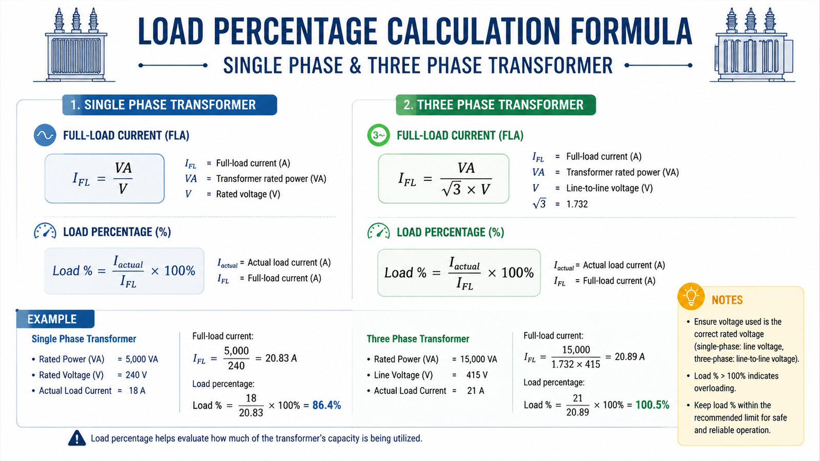
Step 2: Calculate the Full-Load Current
For a einphasig transformer:
Full-load current (A) = VA ÷ Voltage
For a dreiphasig transformer:
Full-load current (A) = VA ÷ (Voltage × 1.732)
Example: a 2000 VA single-phase transformer with a 220 V secondary has a full-load current of 2000 ÷ 220 ≈ 9.1 A.
Step 3: Measure or Estimate the Actual Load
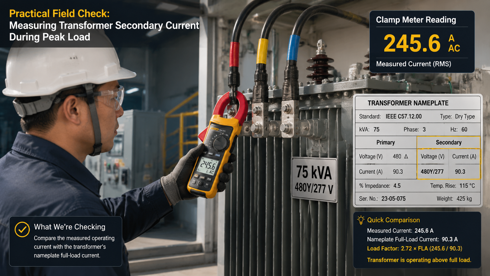
Use a clamp meter on the secondary conductors to read the real operating current during the busiest period of the day — a transformer is judged by its peak load, not its average. If the unit is not yet installed, estimate the load by adding up connected equipment and converting watts to VA with the power factor formula above.
Step 4: Compare Load with the Rating
Express the measured load as a percentage of rated capacity:
Load (%) = (Actual load in VA ÷ Rated VA) × 100
Above 100% means the transformer is overloaded. Between 85% and 100%, the unit is running close to its limit and needs monitoring or a planned upgrade.
Transformer Loading Levels at a Glance
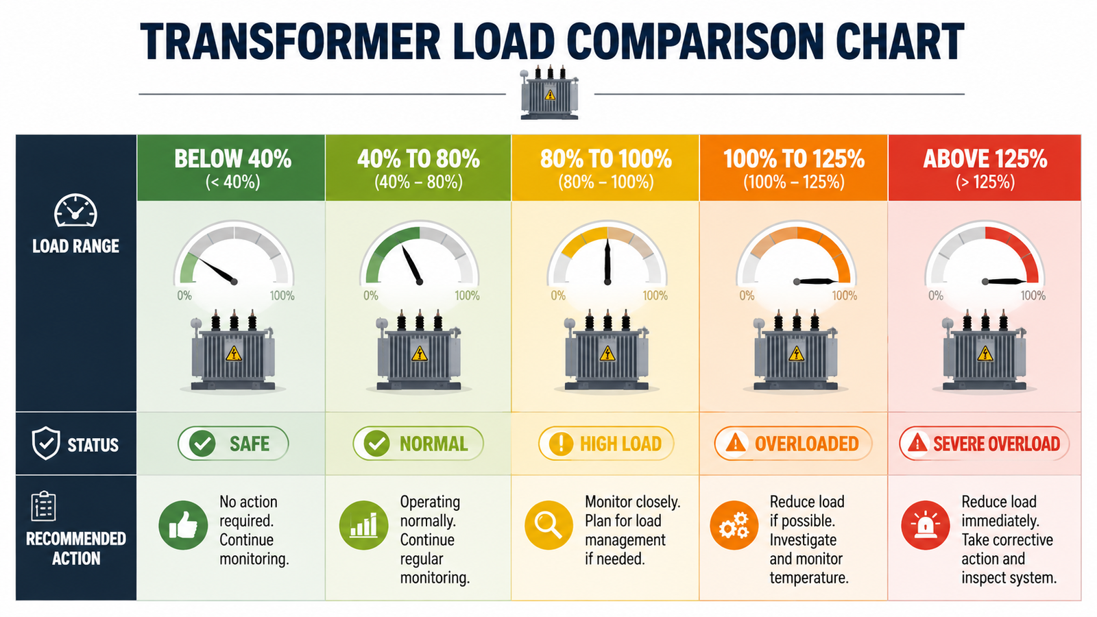
The table below is a practical reference for judging any loading result, covering the dry-type and small encapsulated transformers common in control panels and step up/step down applications.
| Loading Level |
Condition |
Recommended Action |
| Below 40% |
Underloaded |
Operating, but efficiency is poor; consider a smaller unit if permanent |
| 40–80% |
Healthy range |
Normal continuous operation; best efficiency zone |
| 80–100% |
High loading |
Monitor temperature and voltage; plan capacity for future growth |
| 100–125% |
Overload (short-term only) |
Acceptable briefly per manufacturer data; do not run continuously |
| Above 125% |
Severe overload |
Reduce load immediately or replace with a larger transformer |
How Much Overload Can a Transformer Handle?
Short-duration overloads above 100% are sometimes permitted, but only within manufacturer limits and only when the unit ran below full load beforehand. As a guideline, a transformer may tolerate roughly 125% of rating for a short period measured in hours, depending on prior load, ambient temperature, and cooling. These allowances exist for emergencies such as losing a parallel unit — not for continuous overload.
Three factors decide how much abuse a transformer can absorb:
- Ambient temperature. A unit in a hot enclosure or direct sunlight has less margin before its insulation limit is reached.
- Prior loading. A transformer already running at 90% has almost no spare thermal capacity for an overload event.
- Cooling and ventilation. Blocked airflow or dust-covered fins sharply reduce overload capability.
If a transformer is pushed into overload territory, the correct response is load reduction, improved cooling, or a larger unit — not continuous operation at 110% and hoping for the best. For adjustable-voltage test work where loads change constantly, a TDGC2J series variable transformer lets you ramp voltage gradually and observe current draw — a safer way to characterize a load before committing it to a fixed transformer.
Transformer Sizing: Build in Headroom from the Start
The best way to avoid overload is to size the transformer correctly before purchase. The widely used rule is to select a unit rated at least 125% of the calculated maximum load. A 1000 VA calculated load therefore points to a 1250–1500 VA transformer, giving room for motor starting surges, voltage fluctuations, and future additions.
When you apply the 125% rule:
- Use the peak demand, not the average, as the basis for the calculation.
- Apply a realistic power factor rather than assuming 1.0 for inductive equipment.
- Account for inrush: motors can draw 5–8 times running current for a fraction of a second during startup.
- Leave margin for expansion so the next piece of equipment does not force a second purchase.
Review the load first, then match the duty. The same discipline that prevents overload also produces the most economical purchase — neither oversized nor borderline. Buyers who want to confirm real-world behavior before committing often pair a fixed unit with a variable supply for bench testing, keeping the production transformer safely inside its low-voltage transformer window.
Common Load Calculation Mistakes
Even experienced engineers slip on the same few points:
- Sizing from connected load instead of demand. Not every machine runs at once; apply a diversity factor for realistic peak demand.
- Ignoring power factor. Adding up watts and treating them as VA underrates motors and other inductive loads.
- Measuring at the wrong time. A reading during a quiet shift misses the true peak.
- Mixing single-phase and three-phase math. The wrong formula changes the result by a factor of 1.732.
- Treating short-time overload allowance as continuous capacity. The 125% figure is an emergency limit, not a design point.
Final Thoughts on Transformer Load Calculation
Calculating the overload of a transformer comes down to one comparison: the actual load in VA or amperes against the nameplate rating. Keep the load below about 80% for continuous duty, treat anything above 100% as urgent, and size new purchases with a 25% safety margin. A few minutes with a calculator and a clamp meter will protect both the transformer and everything connected to it.
Selecting a unit for a specific machine or control panel? Contact us with your load details and the Johsun engineering team will help match a transformer to your application.
Häufig gestellte Fragen
How do I know if my transformer is overloaded?
Measure the secondary current with a clamp meter during peak load and compare it with the full-load current from the nameplate (VA ÷ voltage, or VA ÷ (voltage × 1.732) for three-phase). Measured current above the full-load value means overload.
What happens if a transformer is overloaded?
Winding temperature rises above the design limit, insulation ages faster, voltage regulation worsens, and the transformer may trip, smoke, or fail permanently — even when it does not fail immediately, service life is shortened.
Can a transformer run at 110% load?
Only briefly, within the manufacturer’s overload curve and usually after running below full load. Continuous operation at 110% shortens insulation life noticeably.
How much load can a 1000 VA transformer handle?
A 1000 VA transformer can supply 1000 VA continuously, about 4.5 A at 220 V. A resistive 800 W load at unity power factor is 80% loading; the same 800 W motor at 0.8 power factor needs 1000 VA, reaching 100% of rating.
Why are transformers rated in kVA and not kW?
Because winding heating depends on apparent power (voltage × current), which includes reactive power that does no useful work. The kVA rating reflects what the windings carry regardless of the load’s power factor.
Should I buy a transformer larger than my calculated load?
Yes — choose a unit rated about 125% of the calculated maximum load. This headroom covers startup surges, voltage variations, and future additions without paying for a drastically oversized unit.
Recommended Models for Transformer Overload Calculation
If you are specifying a unit rather than reading theory, start here. These models cover the capacity bands most often requested for transformer overload calculation, and each links straight to its specification and price range.
Tell us the input voltage, output voltage, phase and continuous kVA you need, and we will confirm the matching model, price and lead time within one business day. Non-standard ratings are handled through OEM/ODM custom transformer manufacturing.