A three-winding transformer has three electrically separate windings on one common core: a primary and two secondaries (or three mutually coupled windings, depending on how the unit is used). These transformers are standard in substations and large industrial plants because one unit can feed two different voltage systems at once, or carry a third “tertiary” winding that does no main power transfer at all but stabilises the unit electrically. This guide explains what makes three-winding transformers different from ordinary two-winding units, how the windings are arranged on the core, why the rated powers of the three windings are not equal, and what to check when selecting or specifying one.
What Is a Three-Winding Transformer?
In the most common configuration, a three-winding transformer connects one primary winding to the high-voltage grid and delivers power through two secondary windings at different voltage levels. A typical substation transformer, for example, might have a 110 kV primary with a 35 kV secondary and a 10 kV secondary, feeding both a distribution network and a local load from the same unit. If the basics of how transformer windings transfer power are new to you, start with our complete guide to transformer coils before reading further. Each winding has its own terminals, tap changer provision, and protection settings, so the three circuits can be loaded and managed independently.
Because all three windings sit on the same magnetic core, the magnetic flux links every winding. This coupling is the source of both the transformer’s usefulness and its complexity: a current drawn by one secondary influences the voltage and current of the other secondary through the shared core, and the leakage reactances between the individual winding pairs determine how the unit behaves under short circuit and sudden load change.
Why Use a Third Winding?
Engineers add a third winding for three distinct reasons, and it is important to know which role a given unit is playing before you try to interpret its nameplate or test report.
Feeding two different load voltages
The most direct use: a plant with both medium-voltage motors (say 6 kV) and low-voltage distribution (400 V) can be fed from one transformer with two secondaries instead of two separate transformers. This saves first cost, floor space, and losses, at the price of more complex protection and slightly larger through-fault currents.
Stabilising the neutral and zero-sequence behaviour
When the third winding is connected in delta (Δ), it provides a low-impedance path for zero-sequence currents and harmonics to circulate within the unit. This keeps the main windings’ neutral stable, reduces third-harmonic distortion in the output voltage, and improves the transformer’s behaviour under unbalanced loads. This delta-connected tertiary is often called a stabilising winding even when no external load is connected to it.
For more on how instrument transformers behave in the same substation environment, see our current transformer in a substation guide.
Connecting auxiliary equipment
A tertiary winding can supply station auxiliaries — cooling fans, lighting, battery chargers — or connect external equipment such as shunt reactors, capacitor banks, or a synchronous compensator that would otherwise need a separate transformer. On large power transformers the tertiary is frequently rated for only 15–30 % of the primary rating, just enough for this auxiliary duty.
Winding Arrangement on the Core
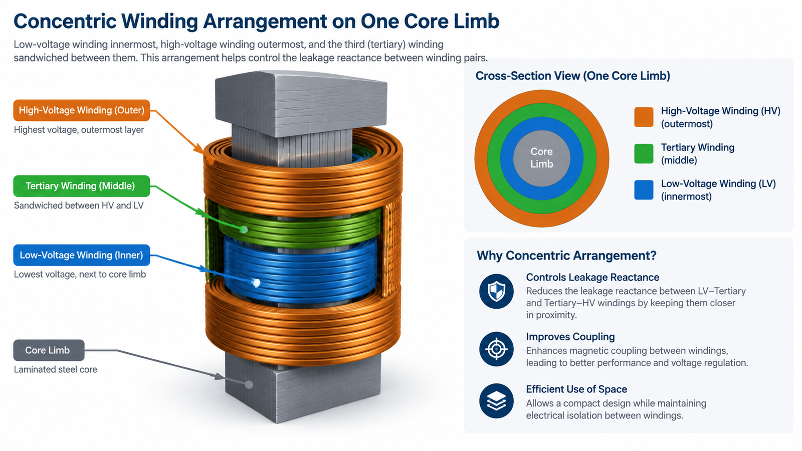
The physical order of the windings on the core limb is not arbitrary; it is chosen to control leakage reactance, mechanical forces, and insulation stress. In the standard concentric arrangement used for most three-winding power transformers, from the core outwards the layers run: low-voltage winding → medium-voltage winding → high-voltage winding (or primary between the two secondaries in some designs).
Placing the low-voltage winding nearest the core gives it the best cooling and the shortest insulation path to earth. The high-voltage winding sits outermost, furthest from the core, because it must withstand the highest voltage to earth and to the other windings. The third winding is sandwiched in between, and its position relative to the other two determines the leakage reactance seen between each winding pair.
Leakage reactance and the three impedances
Unlike a two-winding transformer with a single impedance figure, a three-winding unit is described by three short-circuit impedances: Z12 between winding 1 and 2, Z13 between 1 and 3, and Z23 between 2 and 3. These are measured by shorting one pair at a time and are normally quoted as percentages on a common base. The physical spacing of the windings sets these values: windings placed close together have low leakage reactance between them, while widely separated pairs have high reactance. The arrangement therefore directly controls how much fault current can flow between any two windings and how voltage drops under load transfer from one secondary to the other.
Axial and radial forces under fault
Because three windings share one core, short-circuit forces act on every winding simultaneously. A fault on the 10 kV secondary drives current in both the primary and the 35 kV winding, and the mechanical forces scale with the square of the current. Three-winding transformers therefore need stronger bracing than an equivalent two-winding unit, which is one reason their through-fault ratings deserve close attention in the specification.
Why the Winding Ratings Are Not Equal
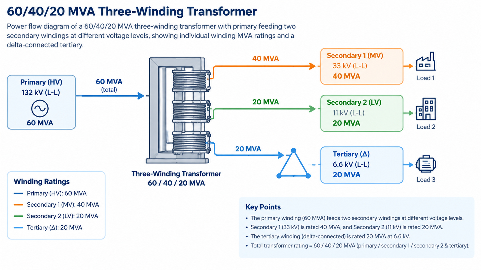
On a two-winding transformer, primary and secondary VA ratings match (minus losses). On a three-winding transformer they deliberately do not. The reason is power flow. If the primary is rated 60 MVA, it may feed 40 MVA through the medium-voltage secondary and 20 MVA through the low-voltage secondary. The primary rating is the sum of the secondary powers it can supply simultaneously, so it is common to see nameplates such as “60/40/20 MVA”.
The tertiary is frequently much smaller still. A stabilising delta winding carries no external load and is often rated at only one-third of the largest winding. Trying to load a tertiary above its rating, or assuming all windings are equal, is a classic specification error — always read the three individual ratings on the nameplate rather than assuming a single MVA figure applies to all windings.
| Winding | Typical rating | Role | Conexión |
|---|
| Primary (HV) | Largest (e.g. 60 MVA) | Receives supply from the grid | Star (YN) with neutral, or delta |
| Secondary (MV) | Middle (e.g. 40 MVA) | Feeds a major distribution bus | Star or delta per system earthing needs |
| Tertiary (LV) | Smallest (e.g. 20 MVA or less) | Second load bus, auxiliaries, or stabilising delta | Delta (d) for harmonic/zero-sequence control |
Voltage Regulation with Two Secondaries
Load changes on one secondary affect the other secondary’s voltage because both are magnetically coupled through the primary. In practice the interaction is governed by the leakage reactances: the larger the reactance between the two secondary windings (Z23 in the three-impedance set), the stronger the voltage dip on one secondary when the other is heavily loaded. This behaviour matters for voltage-sensitive loads such as drives or UPS systems on one bus while the other bus carries motor-starting surges.
Where tight voltage control is needed, the unit is equipped with an on-load tap changer on the primary (or on the medium-voltage winding). The tap changer regulates the controlled winding’s voltage; the other windings then follow approximately in proportion to their turns ratios. Specifying which winding is the “regulated” one is a design decision that must match the system requirements before the transformer is built, because retrofitting a tap changer later is impractical.
Applications of Three-Winding Transformers
- Transmission and distribution substations — converting one transmission voltage into two distribution voltages, or interconnecting two networks at different levels.
- Generator step-up stations — feeding the grid and station auxiliaries, with a tertiary for harmonics or compensation equipment.
- Industrial plants with mixed voltage systems — a single incoming feeder supplying both medium-voltage drives and low-voltage services.
- Railway and traction supplies — where separate windings feed the traction load and the local station loads.
When the application is a variable supply rather than a fixed two-voltage feed, a variable auto-transformer such as the TDGC2J series may be the simpler choice.
In every one of these roles the engineering question is the same: does the plant genuinely need two independent output voltages from one core, or would separate two-winding transformers be simpler and more reliable? Three-winding units save space and cost when both loads are at the same site, but they concentrate more risk in one asset — the outage of a single three-winding transformer takes down both voltage systems at once.
Key Tests and Specification Checks
When specifying or commissioning a three-winding transformer, confirm the following before acceptance:
- Three impedance values — Z12, Z13, Z23 on a stated common base; do not accept a single impedance figure.
- Individual winding ratings — the MVA of each winding, not just the primary, and the permitted loading combinations.
- Connection group — the vector group of all three windings (e.g. YNyn0+d11), which fixes the phase relationships and neutral earthing options.
- Tertiary duty — whether it is a loaded winding, an auxiliary supply, or a stabilising delta, and its insulation/withstand requirements.
- Manufacturer qualification — confirm the factory has built three-winding units before; not every transformer maker can. See what to check in a power transformer manufacturer.
- Temperature-rise and cooling — three-winding losses distribute differently than two-winding units; confirm the cooling class covers the worst-case simultaneous load.
- Short-circuit withstand — the through-fault rating on each winding pair, and the mechanical bracing provided for three-winding force conditions.
Conclusión
A three-winding transformer is a single-core solution for feeding two voltage systems, stabilising a network neutral, or supplying auxiliaries — but it trades simplicity for a more complex electrical personality. The three numbers that define it are the three short-circuit impedances between winding pairs, and the three ratings on its nameplate are rarely equal. Before you specify one, confirm the winding arrangement and connection group, the individual MVA ratings, the tertiary’s real duty, and the through-fault capability. For the wider family of transformer technologies and how each fits an application, browse the transformer knowledge hub or consult the engineering team directly with your loading diagram.
Preguntas frecuentes
What is a three-winding transformer used for?
It provides two independent output voltages from one primary (such as a 110 kV input feeding 35 kV and 10 kV buses), or carries a tertiary winding for auxiliary supply, harmonic control, or neutral stabilisation in a substation.
What is the third winding called?
The third winding is usually called the tertiary winding. When it is connected in delta and carries little or no external load, it is referred to as a stabilising winding because it gives zero-sequence and third-harmonic currents a path to circulate.
Why is the tertiary winding usually connected in delta?
A delta tertiary provides a closed path for zero-sequence currents and third harmonics, which stabilises the star-connected neutrals of the other windings and produces a cleaner output waveform under unbalanced conditions.
Why are three-winding transformer ratings unequal?
Because each winding serves a different purpose and power flows split between the two secondaries. The primary rating equals the maximum simultaneous power it can supply, and the tertiary may be much smaller when it only handles stabilising or auxiliary duty.
How do you measure the impedance of a three-winding transformer?
You measure three short-circuit impedances — Z12, Z13, Z23 — by short-circuiting one winding pair at a time and feeding the third. The three values together fully describe the voltage behaviour between any two windings.
Can one secondary of a three-winding transformer be loaded without loading the other?
Yes. The two secondaries can be loaded independently within their individual ratings, provided the total primary power does not exceed the primary rating. Load changes on one secondary do, however, cause small voltage changes on the other through the shared core.
Recommended Models for Three-Winding Transformers
If you are specifying a unit rather than reading theory, start here. These models cover the capacity bands most often requested for three-winding transformers, and each links straight to its specification and price range.
Indíquenos la tensión de entrada, la tensión de salida, la fase y los kVA continuos que necesita, y le confirmaremos el modelo adecuado, el precio y el plazo de entrega en el plazo de un día laborable. Las potencias no estándar se gestionan a través de Fabricación de transformadores a medida OEM/ODM.