Connecting a transformer backwards is one of the most common installation mistakes we see, and it almost always starts with the same question: which pair of terminals is the LV and HV side? Get it right and the machine works in either direction; get it wrong and a 110 V winding fed with 220 V can saturate the core and overheat within seconds. The good news is that identifying the high-voltage (HV) and low-voltage (LV) sides takes about two minutes once you know the five field methods below — nameplate, terminal markings, winding resistance, physical construction, and a safe low-voltage injection test.
This guide is written for the small dry-type transformers most of our buyers actually install: 100 VA to 10 kVA step-up and step-down units in machine cabinets, test benches, and export equipment. If you are still selecting a unit, our transformer product range covers the full 100 VA to 10 kVA family, and the worked examples below use a 2 kVA 220 V to 110 V machine as a reference.
What “LV” and “HV” Actually Mean on a Transformer
LV and HV describe the rated voltage of each winding, not which side faces the power supply. The winding designed for the higher voltage is the HV winding; the winding designed for the lower voltage is the LV winding. That designation is fixed at the factory and never moves, no matter how you connect the machine.
This distinction matters because основной и вторичный describe connections, while LV and HV describe construction. The primary is whatever winding you feed from the source; the secondary is whatever winding feeds the load. On a step-down transformer the HV winding is normally the primary. Flip the same transformer into a step-up role and the LV winding becomes the primary — but each winding keeps its own voltage rating. A 220 V winding is rated 220 V whether you use it as input or output.
One clarification most articles skip: in the IEC voltage-class sense, “low voltage” means up to 1,000 V AC, and the 110/220 V machines discussed here are all low-voltage class equipment. When a datasheet says “HV side,” it means the higher-voltage winding of that specific machine — not utility-grade high-voltage gear. With that cleared up, here is how to tell the two sides apart.
Five Ways to Identify the LV and HV Side
1. Read the Nameplate First
The nameplate is the authoritative answer and takes ten seconds. Look for two voltage ratings: the higher figure belongs to the HV winding, the lower to the LV winding. A plate marked “220 V / 110 V, 2000 VA” tells you the 220 V terminals are HV and the 110 V terminals are LV. The full-load currents confirm it: 2,000 VA ÷ 220 V ≈ 9.1 A on the HV side, and 2,000 VA ÷ 110 V ≈ 18.2 A on the LV side — the LV winding carries roughly twice the current of the HV winding on the same machine.
If you are new to reading transformer plates, our guide on Как читать паспорт трансформатора walks through every field in order. When the plate is missing or illegible, move to the methods below.
2. Check the Terminal Markings
Industrial dry-type transformers follow a standard marking convention: HV terminals are numbered H1, H2 (and H3 on tapped units), while LV terminals are marked X1, X2. The letter is the giveaway — H always designates the higher-voltage winding, X the lower-voltage one. The numbering order (H1 before H2) also carries polarity information for parallel operation, but for identification purposes the letters alone settle the question.
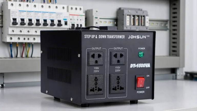
Compact step-up/step-down converters built for international equipment often skip H/X markings entirely and label their outlets instead: two 110 V receptacles and two 220 V receptacles on the front panel. There the labels do the same job — the 220 V outlets are the HV side. Just be careful with units that also expose raw terminal strips: the strip may belong to a different winding or tap, so measure rather than assume.
3. Measure the Winding Resistance
With the transformer de-energized and all loads disconnected, a multimeter on the ohms range tells you which winding is which in one measurement each. The HV winding has more turns of thinner wire, so it reads significantly higher resistance than the LV winding. On a 2:1 machine the ratio is close to the square of the voltage ratio — roughly 4:1:
| Winding |
Rated voltage |
Full-load current |
Measured DC resistance* |
| HV winding |
220 V |
≈ 9.1 A |
≈ 18 Ω |
| LV winding |
110 V |
≈ 18.2 A |
≈ 4.5 Ω |
*Typical values for a 2 kVA double-wound unit measured at room temperature; your readings will vary with rating and copper temperature, but the pattern — one winding several times higher than the other — is what identifies the sides.
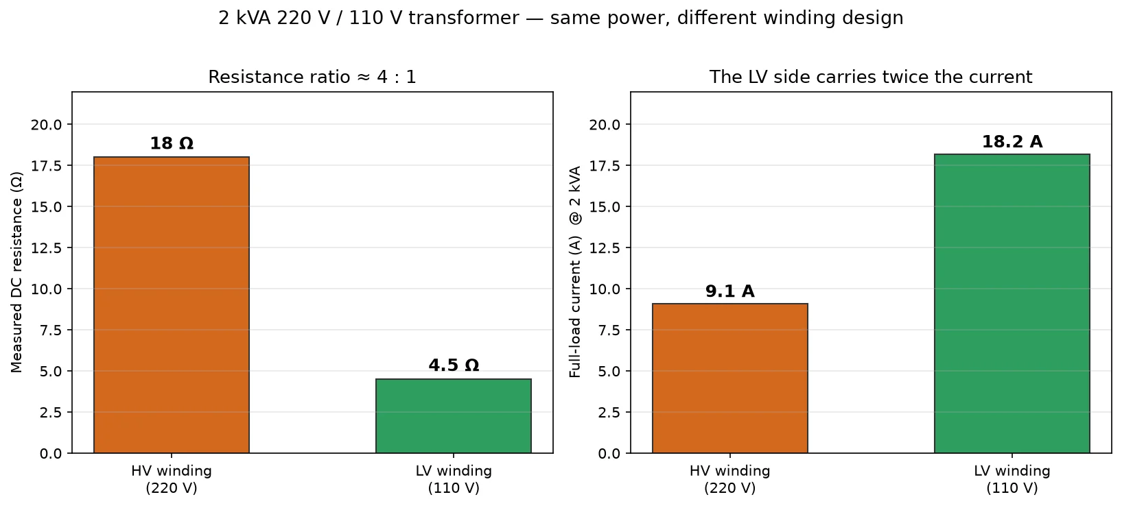
Keep two cautions in mind. First, measure both windings with the same meter at about the same time — resistance rises with temperature, and comparing a cold winding against a warm one distorts the ratio. Second, on very small transformers the LV winding can read under 1 Ω, near the accuracy limit of cheap meters, so treat low readings as “low” rather than exact. For a deeper treatment, see our article on measuring DC resistance of transformer windings.
4. Compare Wire Thickness and Winding Position
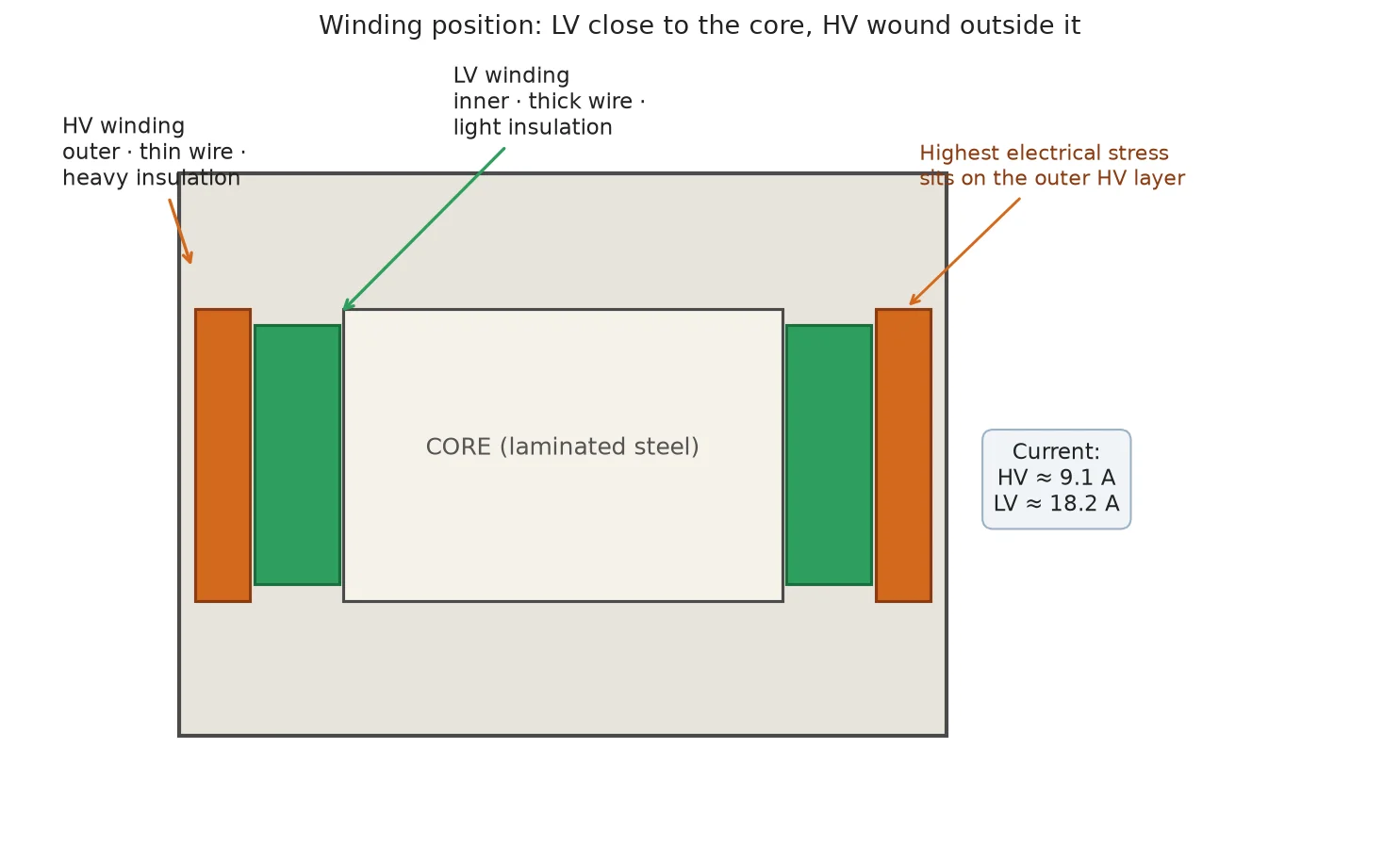
If the unit is open-frame or you can see the windings through the ventilation slots, construction tells the same story. Because both windings carry the same power, the low-voltage winding carries more current and is wound with thicker wire and fewer turns; the high-voltage winding uses thinner wire, more turns, and heavier insulation. The LV winding also sits closer to the core, with the HV winding wound over it — the outer layer needs the extra insulation because it faces the highest electrical stress.
Use the terminal count trick with care: small multi-tap transformers often expose three or more leads on the LV side (for 100/110/120 V selections) while the HV side shows only two. That pattern holds for many units, but taps exist on both sides depending on design, so treat lead count as a hint to verify — never as proof.
5. Run a Safe Low-Voltage Injection Test
When markings and measurements still leave doubt, energize the transformer from a low, safe source and let the ratio identify the sides. This is the most conclusive method, and it is safe if you keep the test voltage small:
- Disconnect every load and confirm the unit is not connected to mains power.
- Feed a low AC voltage — 12 V from a doorbell or lighting transformer works well — into the winding you believe is LV.
- Measure the voltage on the other winding.
- Read the ratio. On our 2 kVA reference machine, 12 V into the 110 V winding produces about 24 V on the 220 V winding; 12 V into the 220 V winding produces about 6 V on the 110 V winding.
The winding that produces the higher voltage from the same 12 V input is the LV winding — it has fewer turns, so the other winding’s larger coil develops more voltage. Never test by connecting an unknown winding directly to rated mains: if you have guessed wrong, you are overexciting a winding beyond its rating with no current limiting. The 12 V injection makes that mistake impossible.
The Special Case: Dual-Voltage Step-Up/Down Transformers
Buyers of international equipment face one variant the generic guides never cover: a conversion transformer with both 110 V and 220 V outputs on the same frame. A typical unit in the STU step-up and step-down series presents four outlets — two 110 V, two 220 V — from two fully isolated windings, and is designed to be used in either direction: feed 220 V in and draw 110 V out, or feed 110 V in and draw 220 V out.
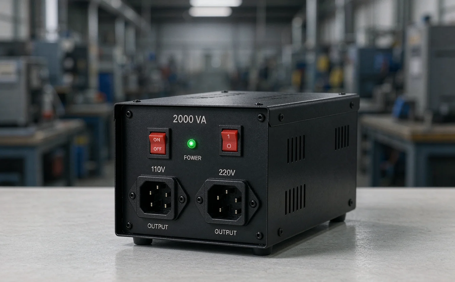
On these machines the identification rule stays simple: the 220 V winding is the HV side regardless of which direction you use it. What changes between step-up and step-down use is only which winding faces the source. What never changes is each winding’s voltage rating — the 110 V winding must never see 220 V at its terminals, no matter which side of the machine it is on. This is also why the outlet labels, not the plug position, are the authority: plugging into the wrong receptacle is exactly the overvoltage fault described below.
What Happens If You Connect the Wrong Side
The consequences are strongly asymmetric, which is why the identification methods above are worth two minutes of your time.
220 V into the 110 V winding (the dangerous case): winding voltage and core flux rise together, and the flux that was sized to run just below saturation now pushes the core deep into saturation every cycle. Magnetizing current jumps to many times its normal value, the winding heats rapidly, and the hum turns from a steady note into a strained growl. Damage begins within seconds to minutes and typically ends in insulation failure or a burned winding — the same failure chain we describe in what causes a transformer to blow, with core saturation as the mechanism in transformer core saturation.
110 V into the 220 V winding (the harmless case): the core runs at half its designed flux, so nothing saturates and nothing overheats. The machine simply delivers half its rated output voltage, with noticeably poorer voltage regulation under load. It is a mistake, but a survivable one — which is why “it still runs” is not evidence that the sides were identified correctly.
| Ситуация |
Best identification method |
Risk if wrong |
| Nameplate legible |
Read the plate (Method 1) |
None — authoritative |
| Terminals marked H/X |
Letter markings (Method 2) |
None — authoritative |
| Unmarked unit, meter available |
Winding resistance (Method 3) |
Low — read-only test |
| Open frame, windings visible |
Wire and position (Method 4) |
Low — visual only |
| Everything uncertain |
12 V injection test (Method 5) |
None at 12 V test level |
| Dual-voltage converter |
Outlet labels: 220 V = HV side |
High — see overexcitation above |
Заключение
The LV and HV sides of a transformer are fixed by winding construction, and any one of five checks settles them: the nameplate voltages, the H and X terminal markings, the resistance ratio between windings, the wire thickness and winding position, or a low-voltage injection test. On dual-voltage step-up/step-down converters, the 220 V winding stays the HV side in either direction of use — the one connection that is never allowed is putting a winding on a voltage above its rating. If you are unsure which configuration fits your equipment, связаться с нами with your supply voltage and load, and we will help you size and connect the right unit.
ЧАСТО ЗАДАВАЕМЫЕ ВОПРОСЫ
Is the primary always the HV side of a transformer?
No. The primary is whichever winding connects to the power source. On a step-down transformer the HV winding is normally the primary, but the same machine used as a step-up unit has its LV winding as primary. Primary describes the connection; LV and HV describe the winding ratings, which never change.
How do I find the HV side of a transformer with no nameplate?
Measure the DC resistance of both windings with a multimeter — the higher-resistance winding is the HV side. For certainty, follow up with a 12 V AC injection test: the winding that generates the higher output voltage from the same input is the LV winding.
Why does the LV winding use thicker wire than the HV winding?
Both windings carry the same power, so the lower-voltage winding carries proportionally more current. More current needs more copper cross-section to keep losses and heating down, which is why the LV winding uses fewer turns of thicker wire while the HV winding uses more turns of thinner, better-insulated wire.
What do H1, H2 and X1, X2 mean on transformer terminals?
By convention, H-designated terminals belong to the higher-voltage winding and X-designated terminals to the lower-voltage winding. The numbers indicate polarity — current entering H1 corresponds to current leaving X1 — which matters when paralleling transformers or observing phase relationships.
Does it damage a transformer to connect 110 V to its 220 V winding?
No lasting damage. The core simply runs at about half its designed flux, so the output voltage halves and voltage regulation worsens under load. The reverse — 220 V into a 110 V winding — saturates the core and can destroy the transformer within seconds to minutes.