If a supplier’s datasheet lists a “bushing” and your quotation for a 2 kVA unit doesn’t, something is not wrong — something is simply different. A transformer bushing is the insulated pass-through that carries a current-carrying conductor through the grounded steel wall of a power transformer tank without flashover. It exists to solve one specific problem, and that problem only appears once a conductor has to cross a grounded barrier at voltage. Below roughly 10 kVA, most dry-type units never face it, which is why they have terminal blocks instead. This guide explains what a bushing actually does, what is inside one, how the main types differ, how bushings are specified and why they fail — and closes with an honest decision table so you can tell whether your project needs bushings at all.
What a Transformer Bushing Actually Does
Every oil-immersed power transformer shares the same construction logic: live copper sits inside a grounded steel tank, submerged in oil. The winding terminals still have to reach the outside world, and the only way out is through that grounded tank wall. A bare conductor pushed through a steel hole would concentrate the electric field at the edge of the opening until the oil around it broke down — first as partial discharge, then as a full flashover to the tank.
The bushing is the engineered answer. It is a graded insulation structure — a central conductor, a solid insulating body, and a mounting flange — that spreads the voltage drop gradually along the path from the live conductor to the grounded flange. Instead of one violent stress point at the tank wall, the field is controlled across the whole crossing. In standards language, a bushing must withstand the voltage and impulse levels declared on the transformer nameplate, per IEC 60137: an insulating structure enabling a conductor to pass through a grounded barrier while withstanding the rated voltage and the lightning impulse level the system will throw at it.
That is the whole job. A bushing does not transform voltage, switch anything, or measure anything. It is passive, and precisely because it is passive, it is easy to underestimate — until you learn that bushing failures account for roughly a tenth of major power transformer outages in utility surveys, and that they tend to fail suddenly and energetically rather than gracefully.
The Anatomy of a Bushing
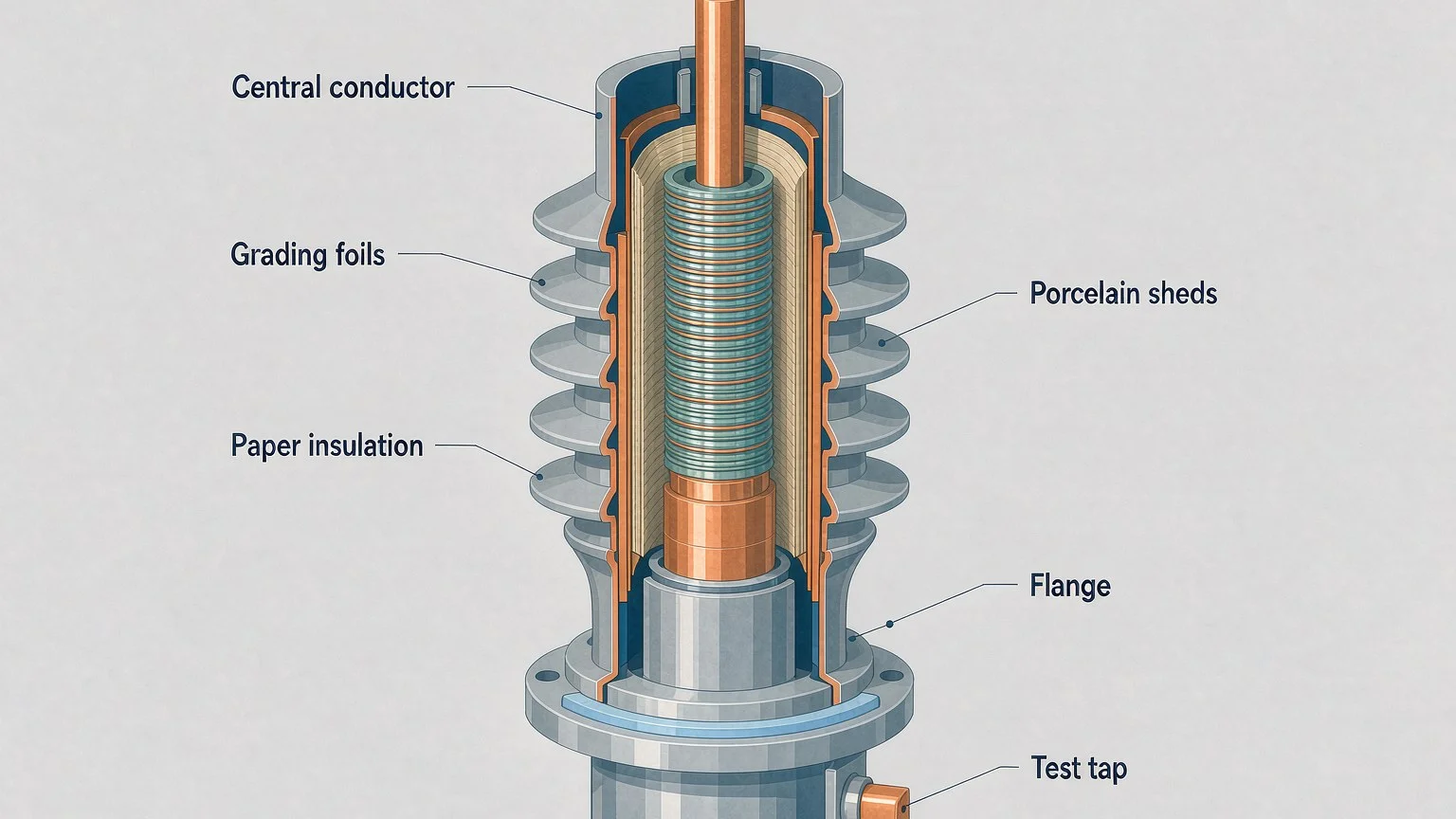
Strip a medium- or high-voltage bushing down to its parts and you always find the same five:
- Central conductor — a copper or aluminium rod or tube, sized for the continuous current plus margin for overload and harmonics. On many designs the winding lead is routed up through a hollow tube (a “draw-lead” connection) instead of being bolted to the bottom.
- Insulation core — the body that holds the dielectric strength. On small distribution classes this is a single solid cylinder of porcelain, cast resin or oil-soaked paper wrap; on condenser designs it is dozens of alternating layers of paper and conductive foil, forming a capacitor divider that grades the field radially.
- Sheds (the insulator surface) — the ribs on the outside, in porcelain or silicone composite. They are not decoration: each shed extends the surface creepage path so rain, salt and dust cannot bridge the insulation externally. More pollution means more creepage, which is why coastal and industrial sites order longer-shed housings.
- Flange and seals — the grounded mounting base clamped to the tank opening. The gasket plane here is the most common entry point for moisture, which makes it the most maintenance-relevant part of the whole assembly.
- Test tap — a small, guarded terminal on condenser bushings (typically above ~34 kV class) that gives access to the last grading layer so maintenance teams can measure capacitance and dissipation factor without de-tanking the transformer.
Bushing Types: Solid, Condenser, Live-Front and Dead-Front
Bushings are sorted by two independent axes: how the insulation inside is built, and how the terminal presents itself outside. Both appear on datasheets, so it pays to keep them apart.
| Классификация |
Тип |
Typical range |
What defines it |
| Internal insulation |
Solid (bulk) type |
Up to ~36 kV |
One homogeneous insulating body — porcelain, cast epoxy or resin-bonded paper. Simple, rugged, cheap; no grading layers, so field control relies on geometry. |
| Condenser (capacitance-graded) type |
Roughly 36 kV and above |
Alternating paper and foil layers grade the field. Subdivided by impregnation medium: OIP (oil-impregnated paper, liquid-filled, lowest cost, needs seal monitoring), RIP (resin-impregnated paper, dry solid, no oil to leak), and the newer RIS (resin-impregnated synthetic, non-hygroscopic core). |
| External termination |
Live-front |
Overhead distribution, open substations |
Exposed bare-metal terminals at full voltage; safe clearances and barriers are the operator’s job. |
| Dead-front |
Pad-mounted and compact units |
Shielded, separable insulated connectors; the energized parts are touch-safe, which is standard for units installed where the public walks by. |
One practical note: a condenser bushing’s grading layers make it a precision capacitive device, not just a lump of insulation. That is why condenser units carry a nameplate capacitance value and a test tap — the two things a maintenance team will trend for the next thirty years. If your specification includes bushings of this class, ask the vendor for the as-measured routine test values; they become your baseline.
How Bushings Are Specified
A bushing is matched to both the winding and the tank opening, so it should never be bought as an isolated commodity. Five parameters do most of the work:
- System voltage and insulation level. The maximum system voltage plus the lightning impulse withstand (BIL) define the internal design. A bushing one class down will survive steady state and die on the first surge.
- Current rating with real margin. Size for continuous load plus overload, harmonics and site ambient — not nameplate kVA alone. Undersized conductors overheat at the terminal, which is a connection problem wearing an insulation costume.
- Creepage distance and pollution class. Driven by the installation site: clean indoor air needs the minimum path; coastal salt, industrial dust or agricultural ammonia demand a longer shed profile. This is where the insulator half of the keyword earns its place — the sheds are literally the external insulator.
- Connection style. Draw-lead (winding lead pulled through the hollow centre) versus bottom-connected rigid stud changes the tank internals, the gasket layout and the spares you hold.
- Interface dimensions. Flange pattern, gasket plane and insertion length must match the tank turret — the classic retrofit trap when substituting a different brand or an OIP-to-RIP upgrade.
Standards matter here in a quiet way. IEC 60137 and IEEE C57.19 series define the tests and tolerances, so a compliant datasheet will show partial discharge, capacitance and tan delta routine test results. A supplier who cannot produce those numbers for a condenser-class bushing is not selling you a bushing; they are selling you a shape. For the surrounding insulation system on the transformer side, the same logic applies as in choosing an insulation class — the parts must agree on temperature and voltage stress, not each be good in isolation.
Why Bushings Fail
Bushing failures rarely arrive without warning; the warning is just easy to miss because it lives in trend data rather than in alarms. The dominant sequence is unglamorous: a gasket ages, moisture creeps in, the paper core absorbs it, dissipation factor rises, partial discharge starts in the damp layers, and the insulation eventually runs away thermally. Low oil level in an OIP bushing after a slow leak is the same story with a faster ending — the uncovered upper section becomes an air gap that cannot withstand the field, and an internal flashover is close to certain.
The second family is thermal and mechanical: a loose terminal stud or an undersized connection overheats, cracks the porcelain or deforms the grading foils, and the capacitance shifts. External flashover from pollution and fog is the third, and it is the cheapest to prevent — washing sheds costs nothing next to replacing a ruptured bushing.
| Symptom you can observe |
Likely mechanism |
Next check |
| One bushing runs noticeably hotter than its neighbours under the same load |
Loose or corroded terminal connection |
Thermographic scan; torque check after de-energizing |
| Oil level window low, or oil staining on the tank below the flange |
Seal leakage on an OIP bushing |
Gasket inspection; plan replacement before the core dries out |
| Capacitance or tan delta drifting up against the factory baseline |
Moisture ingress or partial discharge in the core |
C1/C2 measurement through the test tap; compare with last reading |
| Tracking marks or chalky white deposits on the sheds |
External pollution flashover activity |
Clean and inspect; re-assess creepage class for the site |
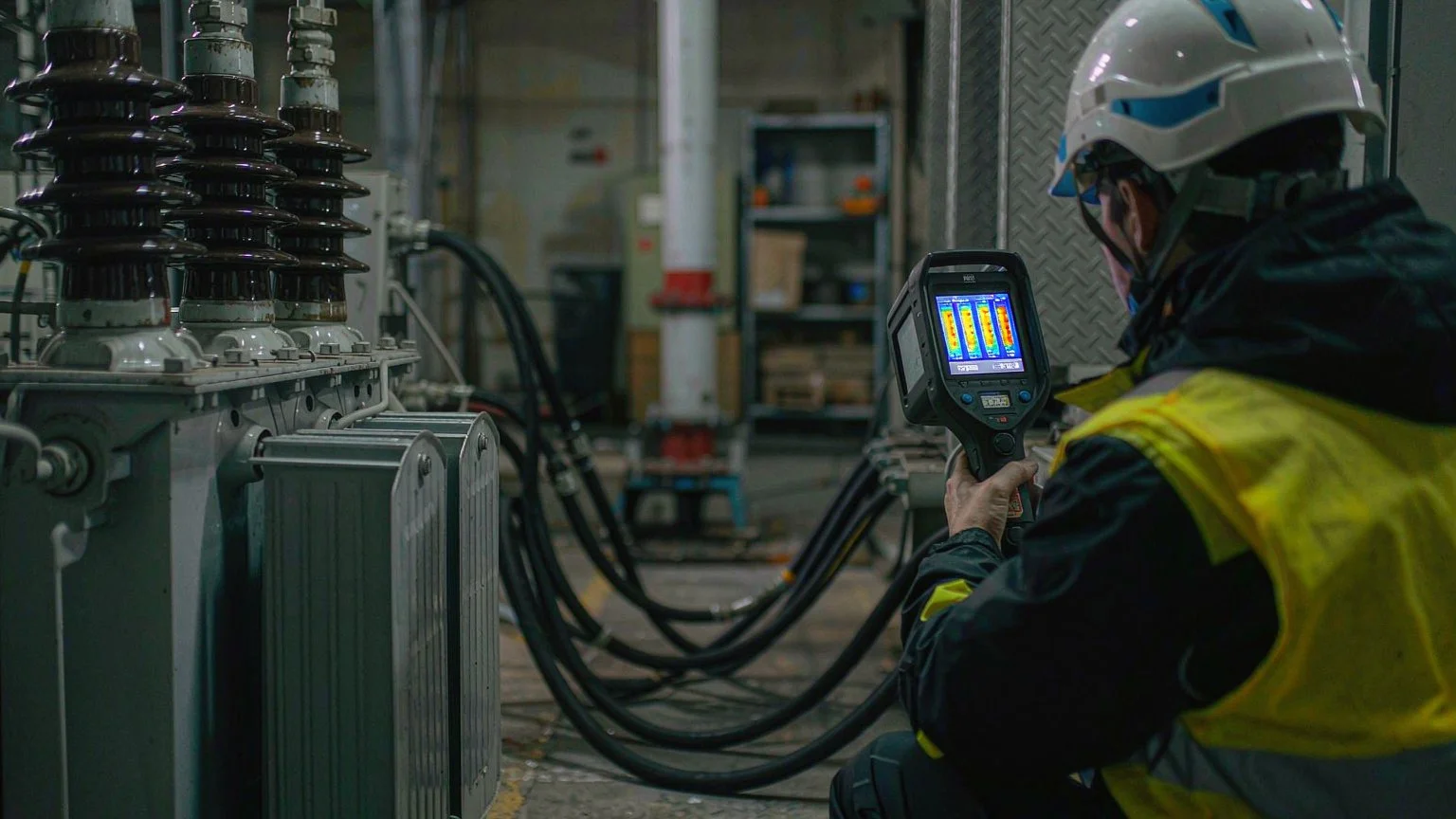
The monitoring habit behind that table is simple and cheap: trend capacitance and tan delta through the test tap during planned outages, scan the bushings with an infrared camera under load once a year, and eyeball the seals and sheds during every site visit. Bushings reward attention earlier than almost any other transformer component, because their degradation is measurable years before it is destructive. This sits naturally alongside the wider picture covered in the dry-type vs oil-immersed comparison and the walk-around sequence in identifying transformer components.
Bushing vs Terminal: What Small Transformers Actually Have
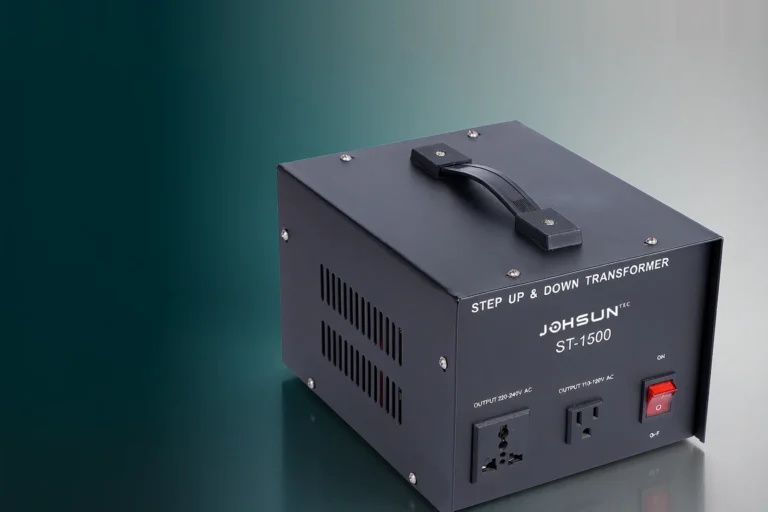
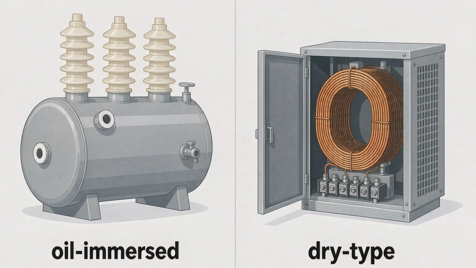
Now the honest part for buyers of smaller equipment. A bushing exists to carry a conductor through a grounded, oil-filled barrier under meaningful voltage stress. A dry-type transformer in a ventilated enclosure has no such barrier: the winding leads land directly on a terminal block or stud board mounted on the enclosure wall, insulated by air and the moulded terminal itself. There is nothing to cross, so there is no bushing — and that is correct engineering, not a missing part.
| Your situation |
What the design should have |
Why |
| Dry-type unit up to ~10 kVA in an enclosure (typical step-up/down, control, isolation units) |
Terminal block / stud terminals with wire lugs |
No grounded oil barrier to cross; air insulation and clearances do the job |
| Oil-immersed distribution unit, pole-mounted or pad-mounted |
Porcelain or composite bushings (live-front or dead-front) |
Conductors must exit a grounded tank; field grading is mandatory |
| Oil-immersed unit at 36 kV class and above |
Condenser-type bushings with test taps and routine test values |
Field stress too high for solid construction; monitoring becomes essential |
The confusion usually starts with vocabulary. A cable gland, a rubber grommet and a standoff insulator are all sometimes called “bushings” in catalogues, but none of them is a transformer bushing in the standard’s sense — they carry cables, not graded voltage. If a quotation for a 2 kVA dry-type unit offers a “bushing upgrade,” the vendor is selling you air. Conversely, if a 35 kV oil-immersed quotation arrives with solid-type bushings and no test reports, walk away. Matching the termination style to the barrier — not to the marketing word — is the whole selection exercise. Our STU series step-up/down transformers, for example, use stud terminals and outlet connections precisely because the enclosure wall is not a grounded oil barrier; the equivalent design decision at distribution voltages is a porcelain bushing on the tank roof.
Заключение
A transformer bushing is a graded insulation pass-through that lets a live conductor cross a grounded tank wall without flashover — nothing more, and nothing less. Everything else follows from that one job: the anatomy (conductor, core, sheds, flange, test tap), the type ladder from solid porcelain to condenser OIP/RIP, the specification parameters (BIL, current margin, creepage, connection style), and the failure modes that all begin with seals or connections. If your transformer has no grounded oil barrier, it needs terminals instead of bushings, and a supplier who explains that honestly is worth more than one who quotes the word. When a specification is unclear, send us the datasheet and we will tell you which side of that line your unit is on.
ЧАСТО ЗАДАВАЕМЫЕ ВОПРОСЫ
What is the main function of a transformer bushing?
To carry a current-carrying conductor through the grounded tank wall of a transformer while insulating it against the rated voltage and lightning impulse level. It grades the electric field along the crossing so no single point concentrates enough stress to flash over.
What is the difference between a bushing and an insulator?
An insulator is any component that prevents unwanted current flow between conductive parts. A bushing is a specific insulating assembly that also provides a mechanical pass-through with a sealed, grounded flange. Every bushing contains insulators — the sheds on the outside — but a standalone insulator does not cross a grounded barrier.
Why do small dry-type transformers have no bushings?
Because their conductors do not cross a grounded, oil-filled barrier. The winding leads terminate on a terminal block inside a ventilated enclosure, where air gaps and clearances provide the insulation. A bushing solves a problem those units do not have.
What is a condenser-type (capacitance-graded) bushing?
A bushing whose insulation core is built from alternating layers of paper and conductive foil, forming a capacitor divider that distributes the electric field evenly. OIP versions are impregnated with oil, RIP versions with cured epoxy resin. They are standard at roughly 36 kV and above and include a test tap for capacitance and tan delta measurement.
How often should bushings be tested?
Visual and infrared checks annually under load; capacitance and tan delta through the test tap during planned outages, typically every 1–3 years depending on criticality and age. Always trend against the factory routine test values rather than judging a single reading in isolation.
Can a damaged bushing be repaired?
External items — gaskets, terminal hardware, sometimes housings — can be serviced, but a condenser core with rising tan delta or shifted capacitance is replaced, not repaired. The grading layers cannot be re-made in the field, and a degraded core is a sudden-failure risk.