Insulation class is the one figure on a transformer label that decides how long the unit will last, and the one buyers most often treat as a quality badge. In practice the letter — A, B, F or H — only states the maximum continuous temperature the insulation system tolerates. Whether a 1.5 kVA step up and step down transformer survives ten years or two depends on three other numbers: the temperature rise the supplier designed to, the air temperature inside the enclosure, and the winding hot-spot gradient. Line those up and you have a defensible insulation class choice; skip them and you hold a datasheet claim that stops being true the first hot summer.
What an Insulation Class Actually Rates
An insulation class is a system rating, not a wire rating. Under IEC 60085 and the UL 1446 system approach it covers every material in the heat path working together: magnet wire enamel, interlayer film, bobbin, impregnating varnish, lead wires, sleeving and terminal block. UL 1446 proves a combination, not a component.
That matters at the small end of the market, where lead wires and terminal blocks are moulded into the coil assembly, so a system is only as good as its weakest part. The class also says nothing about efficiency, voltage accuracy, ingress protection or fire behaviour.
The Four Numbers You Have to Reconcile
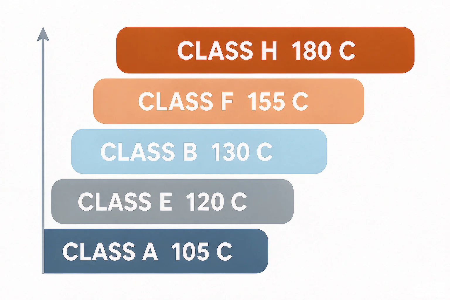
Thermal class is a limit, not an operating temperature. Four values decide whether the unit stays inside it:
- Class limit — the maximum continuous temperature the system tolerates, e.g. 155 °C for Class F.
- Declared temperature rise — how much hotter the winding may get above rated ambient at rated load, usually printed in kelvin.
- Rated ambient — the surrounding air the rating assumes, normally 40 °C maximum with a 30 °C 24-hour average.
- Hot-spot gradient — the difference between the hottest point in the winding and the average, typically 10–20 K on small dry-type units.
Ambient plus rise plus gradient must stay at or below the class limit. Every misapplied class traces back to one of those four values, not to the letter.
| Thermal class |
Maximum continuous temperature |
Typical dry-type rise at 40 °C ambient |
Where you meet it |
| Class Y |
90 °C |
— |
Legacy cotton and paper windings, obsolete |
| A Sınıfı |
105 °C |
55–60 K |
Older oil-filled and impregnated paper designs |
| Class E |
120 °C |
75 K |
Transitional rating, rare on new low-voltage units |
| B Sınıfı |
130 °C |
80 K |
Economy dry-type, light or intermittent duty |
| F Sınıfı |
155 °C |
100–115 K |
The default for modern low-voltage dry-type units |
| H Sınıfı |
180 °C |
125–150 K |
High ambient, heavy duty, tropical and marine |
Why “Class F Versus Class H” Is the Wrong Question
Comparing two quotes by letter is unsafe, because the same letter can hide a 15 K difference in declared rise. Units built to UL and NEMA practice commonly declare 55, 80, 115 and 150 °C rise for Class A, B, F and H; units built to IEC 60076-11 declare 60, 75, 80, 100 and 125 K average rise for A, E, B, F and H. A Class F unit is a 100 K design in one document and a 115 K design in another.
Many manufacturers also build Class F systems at only 60–80 K rise. That is not under-specification; it is a cheap way to buy margin, since a lower rise costs extra copper and core rather than high-temperature materials. The result is counterintuitive: a Class F unit at 60 K rise runs its winding near 100 °C at 40 °C ambient, while a Class H unit at 125 K rise runs near 165 °C. The better letter is the hotter machine. Ask for the declared rise as well as the class — the field-by-field method is in transformatörün tip etiketini nasıl okunur.
The Ambient You Should Actually Design To
Almost every misapplied class starts with a room temperature measurement. The transformer lives inside an enclosure next to contactors, drives and heat sinks, and that air is hotter: a ventilated cabinet in a 30 °C plant room runs 10–20 K above room temperature once loaded, a sealed cabinet without dedicated airflow 15–25 K above.
Design against the internal air. Working back from the class limit with a 15 K gradient:
| Internal ambient |
Max usable rise, Class F |
Max usable rise, Class H |
Practical reading |
| 35 °C |
105 K |
130 K |
Any standard Class F unit is fine |
| 40 °C |
100 K |
125 K |
Rated condition, no action needed |
| 45 °C |
95 K |
120 K |
Check the declared rise before accepting the quote |
| 50 °C |
90 K |
115 K |
A 115 K Class F design is already past its thermal limit |
| 55 °C |
85 K |
110 K |
Derate, or specify Class H with a low rise |
| 60 °C |
80 K |
105 K |
Class H with forced ventilation, or a larger frame |
Derating Without Guessing
If the unit already exists and the internal ambient exceeds 40 °C, capacity has to come down. Winding losses scale with the square of current, so usable apparent power scales with the square root of remaining rise: kVA usable ≈ rated kVA × √(available rise ÷ rated rise).
Take a 1.5 kVA Class F unit declared at 100 K rise, in a cabinet that reaches 52 °C in July. Available rise is 155 − 52 − 15 = 88 K, and √(88 ÷ 100) is 0.94, so capacity falls to about 1.41 kVA. The shortcut agrees: 8% of nameplate kVA per 10 °C above 40 °C gives 1.36 kVA.
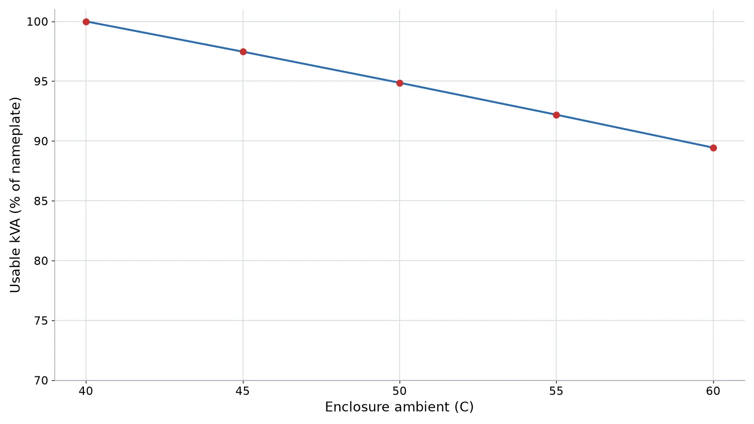
Altitude works the same way: above 1,000 m thinner air carries heat away less effectively and nameplate kVA falls by roughly 0.3% per additional 100 m. Aluminium windings run hotter for the same losses, as covered in copper versus aluminium transformer windings, and feeding a 50 Hz design from 60 Hz adds a further penalty explained in 50 Hz versus 60 Hz transformer limits.
Where Class H Earns Its Extra Cost
| Saha durumu |
Class F enough? |
Reasoning |
| Machine control cabinet, 30–38 °C internal |
Evet |
Margin is already large; spend the budget on a lower rise |
| Laboratory, medical cart, clean room |
Evet |
Stable ambient, light duty, low harmonics |
| Foundry, heat-treat shop, steel mill floor |
Hayır |
Radiant heat plus 45–55 °C air, continuous duty |
| Sealed outdoor kiosk in tropical sun |
Hayır |
Internal air commonly 55–65 °C in the afternoon |
| Engine room, boiler room, laundry |
Hayır |
High ambient combined with humidity and dust |
| Marine, offshore, desert projects |
Hayır |
Class H plus C2 climatic and E2 environmental classification |
| Panel dominated by VFDs and rectifiers |
Sometimes |
Harmonic losses raise winding temperature; K-rated or Class H is safer |
Where Class H does not help is the case people buy it for most often: a sealed cabinet with no airflow and three other heat sources inside. The extra 25 K of ceiling buys one hot summer, then the next one eats it.
Fire Class Is a Different Letter
On IEC 60076-11 dry-type transformers the letter F appears twice. Thermal class F is the 155 °C insulation rating above; fire behaviour class F0, F1 or F2 describes how the unit behaves in a fire and is declared separately, alongside environmental class E0/E1/E2 and climatic class C1/C2. A datasheet line reading “Class F” with no unit is ambiguous, and a spec demanding a “Class F fire rating” from a supplier quoting a thermal class has not been checked at all.
The Component That Usually Fails First
In the 100 VA to 10 kVA range, failures rarely begin in the winding enamel; they begin at the interfaces — lead wire insulation, terminal block bodies and the varnish bond where coil meets bobbin. Ask for the rating printed on the lead wire (AWM 1015 is 105 °C, silicone 180 °C, PTFE 200 °C and above) and confirm the terminal block matches the class you paid for.
How to Verify the Claim at Goods-In
You do not need a laboratory to test a Class F claim — run a load soak and read the case:
- Bolt the unit into the enclosure it will live in, with all other equipment energised.
- Log internal air temperature 100 mm from the case, then load to rated current for two hours until case temperature stops climbing.
- Measure the hottest point on the case — usually the top face above the winding — and add the case-to-winding gradient, typically 15–25 K on a ventilated steel case.
- For the real number, take winding resistance cold and hot: R2 ÷ R1 = (234.5 + T2) ÷ (234.5 + T1) for copper, in Celsius.
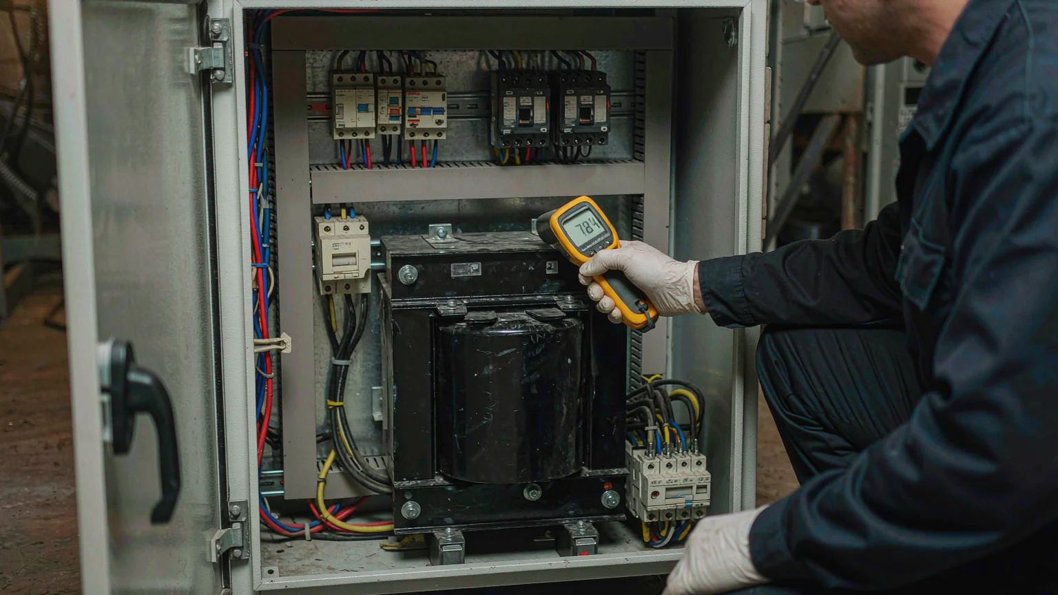
A unit reaching 75 °C on the case in a 40 °C cabinet is normal for Class F. One reaching 90 °C in a 30 °C room is telling you its declared rise is far higher than the datasheet implied. Rising buzz, hot-varnish smell and discoloured lead wire are the in-service versions of that message, catalogued in transformatörün aşırı ısınmasına dair uyarı işaretleri.
A Four-Step Specification Sequence
- Measure internal air temperature of the real enclosure at peak summer load, not the room.
- Set the hot-spot ceiling at the class limit minus 15–20 K for ageing, and convert it into a maximum declared rise.
- Put that rise in the RFQ beside the class letter, with ambient, altitude and fire class.
- Ask for the insulation system listing (UL 1446 or equivalent) and the lead wire and terminal block ratings, then repeat the numbers in the purchase order.
Done properly, transformer insulation selection is a two-line calculation and a short list of questions; done by letter alone it is a coin toss that settles itself three years into service. Our ST-1500VA step up and step down transformer shows what a low-rise, naturally cooled Class F design looks like, and the rest of the range sits in the low-voltage transformer range. Because thermal classes differ by construction, dry-type and liquid-filled units are not directly comparable — see Kuru tip ve yağa batırılmış transformatörlerin karşılaştırılması — and our engineers will confirm the declared rise and ambient assumptions for your site before you order.
SSS
Is Class H insulation better than Class F?
Not automatically. Class H raises the ceiling from 155 °C to 180 °C, but a Class H unit built at 125 K rise runs hotter than a Class F unit built at 60 K rise. Compare declared rise, not the letter.
What does Class F mean on a transformer?
That the insulation system is rated for a maximum continuous winding temperature of 155 °C. It does not mean the unit runs that hot, and it does not define fire behaviour, which IEC 60076-11 declares separately as F0, F1 or F2.
What ambient temperature is a transformer rated for?
Standard ratings assume 40 °C maximum ambient with a 30 °C 24-hour average. Above 40 °C, reduce capacity by roughly 8% of nameplate kVA per 10 °C, or specify a higher class.
Can I run a Class F transformer at 50 °C ambient?
Only if its declared rise leaves room. At 50 °C with a 15 K gradient the usable rise is 90 K, so a 100 K or 115 K design must be derated while a 60–80 K design still runs at full load.
How do I find the insulation class of a transformer I already own?
Look for INS CLASS or CL on the nameplate. If the plate is missing or unreadable, a resistance-method temperature rise test at rated load shows what the unit actually does.