From the outside, every power transformer is a black box: a steel tank, some porcelain, a few gauges and pipes. Most guides that list power transformer components present them alphabetically, which is not the order you actually meet them in. On a site visit or during incoming inspection, you meet the components in a fixed sequence: nameplate first, then the tank fittings, then the bushings, then the tap changer — and the core and windings last, because you usually infer them from tests rather than see them. This guide walks through the four component groups in that order, separates what you can see from what you can only test for, and closes with the visible symptoms that point to a specific internal part. For broader context, the Transformer Bilgi Bankası covers the surrounding topics from sizing to testing.
Start With the Nameplate, Not the Tank
Before you identify a single component, read the nameplate. It tells you what to expect inside: the kVA rating, primary and secondary voltages, connection group, impedance, cooling class and insulation class. The cooling class is the most useful line for this exercise. ONAN or ONAF means an oil-immersed unit with radiators; AN or AF means a dry-type unit, possibly with fans. If the plate says dry-type, roughly half of the classic internal parts list — transformer oil, conservator tank, Buchholz relay, oil-filled bushings — simply does not exist on that unit, and inspecting for them wastes your time.
Three fields are worth photographing before you walk around: cooling class, insulation class, and tap range (typically ±2 × 2.5%). We decode all of them in transformatörün tip etiketini nasıl okunur.
The Four Component Groups That Matter
Everything inside a transformer belongs to one of four jobs: the magnetic circuit (core), the electrical circuit (windings and leads), the interface between the inside and the outside world (bushings or terminals), and the regulation subsystem (tap changer). Oil, radiators, fans and sensors exist only to support these four. The table below is the fastest way to orient yourself on any unit.
| Group |
Components |
Job in one line |
Checkable without opening the tank |
| Magnetic circuit |
Laminated core, core clamps, core ground strap |
Carries magnetic flux between the windings |
No-load loss on the test report, noise, vibration |
| Electrical circuit |
HV and LV windings, internal leads, inter-winding insulation |
Transforms voltage by turns ratio |
Ratio test, DC resistance balance, insulation resistance |
| Arayüz |
Bushings or terminal blocks |
Passes conductors safely through the grounded tank |
Visual: cracks, tracking marks, oil seepage |
| Yönetmelik |
Off-circuit or on-load tap changer |
Trims output voltage by changing tap positions |
Position indicator, operation counter, contact resistance |
The Core: What You Infer Rather Than See
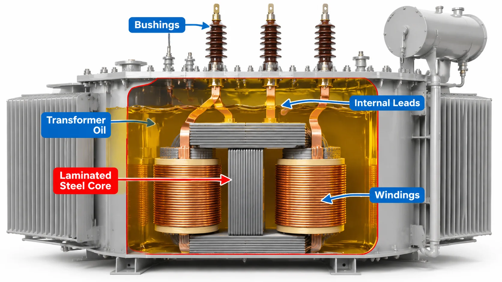
The core is a stack of thin grain-oriented silicon steel laminations, typically 0.23–0.35 mm thick, assembled with step-lap corner joints and clamped under pressure, with exactly one deliberate ground strap. On an oil-filled unit it sits fully submerged at the bottom of the tank; on a sealed dry-type unit it is encapsulated in resin. In both cases you will almost never see it, so you judge it by proxies. The core and iron structure guide explains the construction itself; for condition assessment, watch these four things:
- No-load loss on the factory test report. This single number reflects both the lamination grade and the quality of the build. Compare it between suppliers for the same rating.
- Sound quality. A healthy core produces a uniform hum. A rattling or uneven noise suggests loose clamping.
- Vibration. Increasing vibration over time on an aging unit points to loosening core structure.
- Core ground resistance. It should read near zero at one point and only one point. A second, accidental ground path creates a circulating current loop and localized heating.
If you ever see a unit opened, inspect the clamping: loose bolts or degraded banding let laminations vibrate at twice the line frequency, abrading each sheet’s insulation coating and producing hot spots no external test will localize.
The Windings: Read the Outside of the Coil First
In the standard concentric arrangement, the low-voltage winding sits closest to the core leg and the high-voltage winding wraps around it, separated by pressboard barriers and cooling ducts. The HV winding uses more turns of thinner conductor; the LV winding uses fewer turns of thicker conductor. Whether that conductor is copper or aluminum is a legitimate design choice with real cost and weight trade-offs — we compared them in copper vs aluminum windings.
Like the core, the windings stay hidden on sealed units. You verify them from the outside with three tests: a turns ratio test (which also validates each tap position), a DC resistance measurement per phase or per winding (an imbalance catches turn-to-turn shorts and bad joints), and an insulation resistance test between windings and to ground. One habit matters more than the instruments: record the tap position before any test, because the ratio changes with every tap step. The procedure is in how to test transformer turns ratio.
The insulation class printed on the nameplate — A (105°C), F (155°C) or H (180°C) — tells you how much thermal margin the winding was built with, and how hard you can load it before insulation aging accelerates.
Bushings: Where the Winding Meets the Outside World
A bushing is the insulated pass-through that carries a conductor through the grounded tank wall without flashover. At distribution voltages you will see solid porcelain or polymer housings; at higher transmission voltages, condenser-type bushings (oil-impregnated paper or resin-impregnated paper) with test taps and monitored capacitance. A walk-around catches bushing problems earlier than any scheduled test: cracks or chips in the porcelain, carbon tracking paths from surface pollution, oil weeping at the flange gasket, and discoloration at the terminal connection from loose-lug heating. Bushing construction, creepage selection and capacitance testing are a topic of their own, so we will keep this section to identification level.
One honest note for buyers of smaller equipment: on dry-type units below roughly 10 kVA, there are no bushings at all. The conductors land on a terminal block mounted on the enclosure wall. If a quotation for a 5 kVA step-up/down unit prices a “bushing upgrade,” the vendor is selling you air.

The Tap Changer: The Only Moving Part You Can Reach
Two families exist. The off-circuit tap changer (often called DETC) is a manual handwheel or lever with numbered positions — usually five — and may only be operated with the transformer de-energized. The on-load tap changer (OLTC) is motor-driven and changes taps while carrying load, using a diverter switch housed in its own oil compartment. On large units the OLTC is statistically the most maintenance-hungry subsystem: its contacts wear, its compartment oil degrades, and its drive mechanism miscounts.
For identification purposes, three things matter. Find the position indicator and record the number before any test. Check whether the nameplate lists a tap range at all — small dry-type units usually have fixed taps and no changer. And never rotate a DETC while energized: the contacts will draw a sustained arc and the next tap change may be your last one on that unit.
What a Walk-Around Actually Reveals
Visual inspection will never replace electrical testing, but it reliably points you to the right component and the right next test. These are the six combinations worth memorizing:
| What you see |
Component implicated |
Next test |
| Oil weeping at a bushing flange |
Gasket or seal |
Bushing power factor; plan seal replacement |
| Carbon tracking on porcelain |
Bushing surface / creepage shortfall |
Insulation resistance; clean or upgrade for the site’s pollution level |
| Pink silica gel in the breather |
Breather saturated |
Oil moisture content (Karl Fischer) |
| Paint discoloration above a terminal |
Loose lug or connection heating |
Thermography under load, then DC resistance |
| Loud or uneven hum, new rattle |
Core clamping |
Vibration check and no-load current against baseline |
| OLTC operation counter jumping or erratic |
Drive mechanism |
Dynamic resistance measurement of contacts |
Component Visibility Depends on the Transformer Type
How much of the component list physically exists — and how much of it you can inspect — depends entirely on which of the three construction families you are facing. This is also where component lists written for utility-scale units mislead buyers of smaller equipment:
| Bileşen |
Oil-immersed distribution |
Sealed dry-type (cast / VPI) |
Small dry-type (100 VA–10 kVA) |
| Çekirdek |
In tank, not visible |
Encapsulated, not visible |
Enclosed, not visible |
| Sargılar |
In tank, not visible |
Encapsulated, not visible |
Enclosed, not visible |
| Bushings |
Porcelain on the cover |
Terminals through epoxy panels |
Terminal block only |
| Tap changer |
DETC or OLTC with indicator |
Usually fixed taps |
Yok |
| Conservator, Buchholz relay |
Present on larger units |
Yok |
Yok |
Four Identification Mistakes That Cost Time
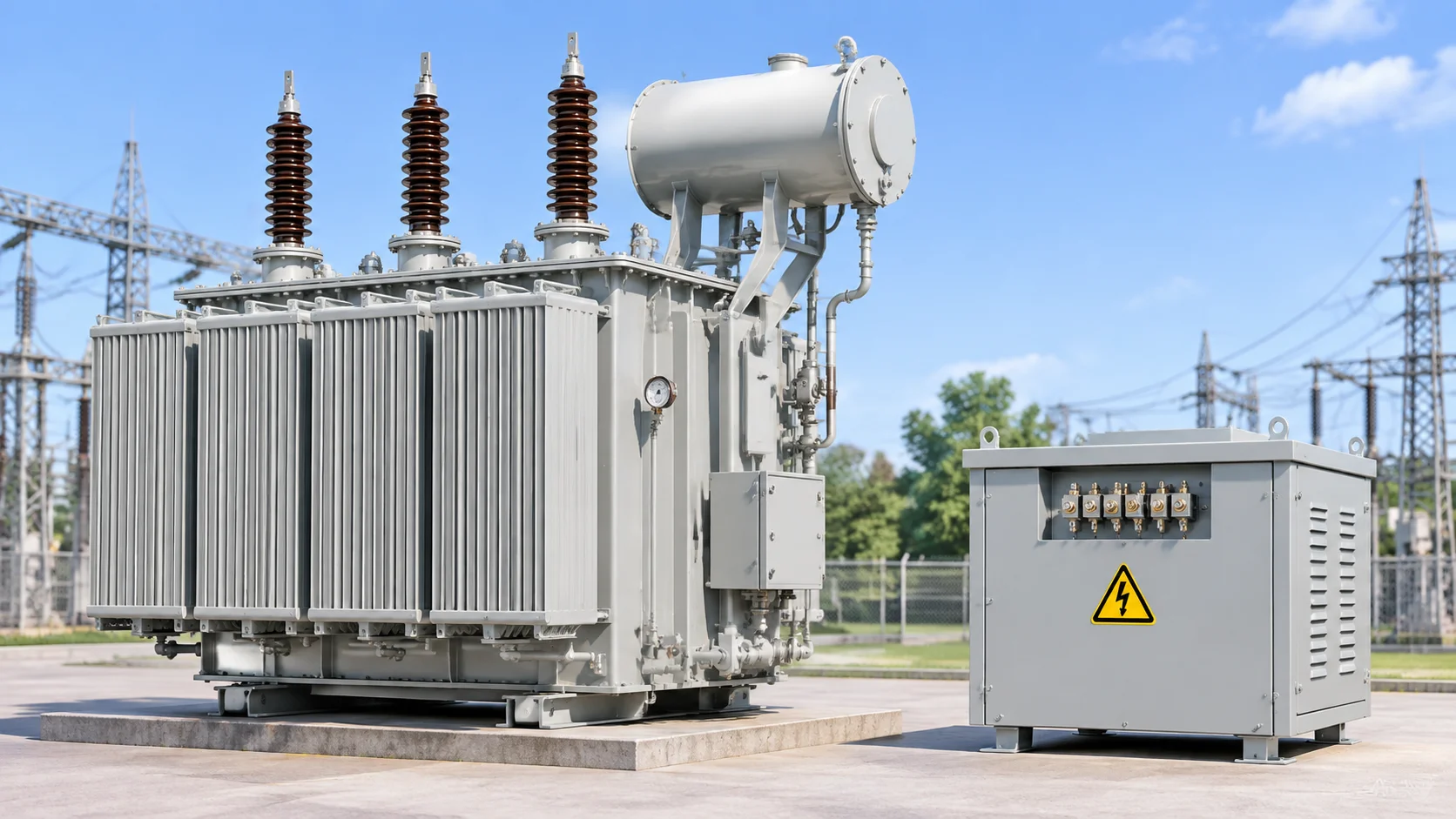
- Calling the conservator an “expansion tank for cooling.” It compensates for oil volume change with temperature; the actual cooling happens in radiators and fans.
- Treating enclosure fins on a dry-type unit as winding cooling. They ventilate the enclosure; the windings cool through their own resin or impregnation system and internal ducts.
- Confusing a DETC handwheel with an oil valve. One changes the turns ratio (de-energized only), the other drains oil. The handwheel carries numbered position marks.
- Judging winding material by terminal color. Aluminum-wound units routinely use copper terminal lugs. Confirm conductor material on the nameplate or test report, not by eyeball.
Where This Leaves a Buyer
The practical takeaway is a supplier question. Before signing, ask the vendor to name the component-level specifications: core material and build method, conductor material, insulation class, bushing or terminal type, tap range and changer type, and cooling class. A supplier who cannot fill in that list is selling you a black box, no matter how well the paint is applied.
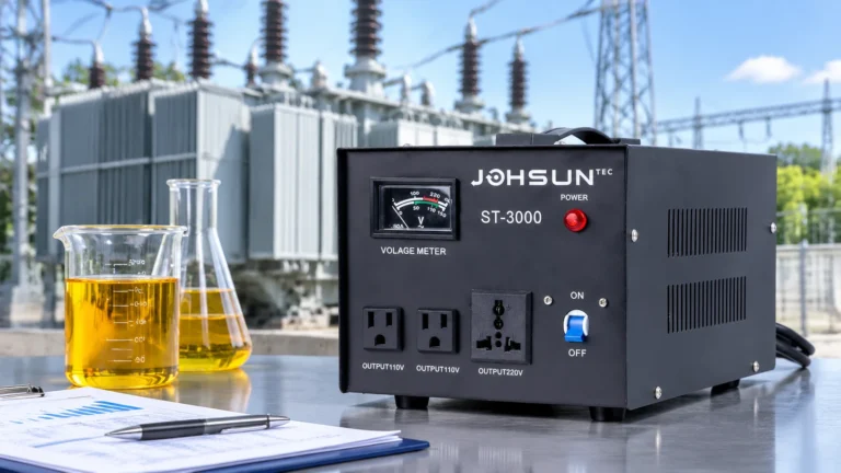
If your application sits in the single-phase 110/220 V conversion range between 500 VA and 10 kVA, the component list is short by design. The DT-5000VA yükseltici ve düşürücü transformatör, for example, is a sealed dry-type unit: laminated core, dual windings, terminal block, no tap changer — and knowing that in advance is exactly what makes its inspection checklist simple. For a component-level datasheet, custom tap ranges or other voltage combinations, talk to our engineering team.
Sonuç
Identifying power transformer components is a matter of order and honesty: nameplate first, then tank fittings, bushings and the tap changer, and only then the core and windings — which you infer through test reports. What you can see points you to the next test; what you cannot see is what the factory test report exists for. Keep the symptom table next to your inspection checklist, and the walk-around will do its real job: telling you which component to interrogate next.
SSS
What are the main components inside a power transformer?
The core, the HV and LV windings with their insulation system, the bushings, and the tap changer. Oil-immersed units add transformer oil, a conservator and protective relays; dry-type units replace oil with resin or vacuum impregnation and ventilation.
Can you see the windings without opening the tank?
No. On sealed units the windings are submerged in oil or encapsulated in resin. You verify their condition with turns ratio, DC resistance and insulation resistance tests instead.
What is the difference between a bushing and a terminal?
A bushing is an insulated pass-through that carries a conductor through the grounded tank wall of larger units. A terminal is a connection point on the enclosure of dry-type and small units, with no tank wall to cross.
Where is the tap changer located?
On oil-immersed units it sits in its own compartment on the tank side or under the cover, with a numbered position indicator outside. Small dry-type units usually have no tap changer at all.
Which component fails most often?
Insulation-related failures dominate the statistics: aging paper insulation, leaking bushing seals and worn tap changer contacts — exactly the three the walk-around and routine oil tests target.