When someone asks about available fault current at a transformer secondary, the answer they find online is usually written for the wrong machine. Most articles and calculators work through 500 kVA to 1,500 kVA distribution transformers, where a bolted fault reaches tens of thousands of amps. If you buy, install, or protect small dry-type transformers in the 100 VA to 10 kVA range — step-up and step-down units in machine cabinets, test benches, and export equipment — the numbers, the risks, and the protection decisions all look different.
This guide runs the calculation the way an engineer does on a real project, but keeps the focus on small single-phase units: one worked example end to end on a 1.5 kVA 220 V to 110 V transformer, what impedance actually limits the current on machines this size, and what the result means for transformer protection — fuse and breaker sizing, interrupting ratings, and the one phenomenon, magnetizing inrush, that trips more small transformers than any real fault ever will. If you are still selecting the unit itself, our transformer product range covers 100 VA to 10 kVA step-up and step-down models, and the example below uses a real 1.5 kVA machine.
What “Available Fault Current” Actually Means
Available fault current is the maximum current the supply can push into a solid (bolted) short circuit at a given point. It is a property of the supply, not of the load connected there. Every protective device downstream must have an interrupting rating at or above this value, which is why the number matters even in systems where a fault is unlikely.
At a transformer secondary, the standard first estimate assumes the primary supply is an infinite bus — a zero-impedance source that holds its voltage no matter how much current the fault draws. Under that assumption, only the transformer’s own impedance, written as %Z, limits the fault:
Isc = FLA × 100 / %Z
where FLA is the rated full-load secondary current. A 5% transformer delivers 20 times rated current into a dead short; 10% delivers 10 times; 20% delivers only 5 times. The relationship is explained in depth in our article on transformatör empedans yüzdesi, so here we go straight to using it. The infinite-bus result is always an upper bound — real sources have some impedance, so the true fault current is slightly lower.
The Calculation, Step by Step
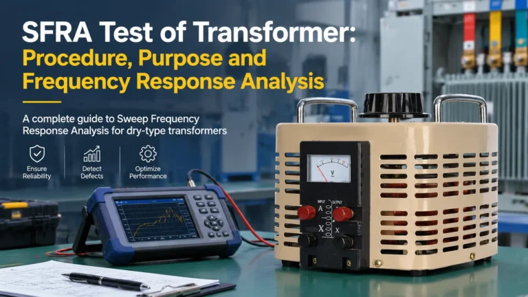
Take the machine from the cover of this article: a 1.5 kVA single-phase step-up/step-down transformer with a 110 V output winding, fed from a 220 V supply. Three steps:
Step 1 — rated secondary current. For single-phase units, FLA is simply VA divided by secondary voltage:
FLA = 1500 VA / 110 V = 13.6 A
Step 2 — the impedance. This is the step most guides skip, because large distribution transformers always have %Z on the nameplate. Small dry-type units usually do not. A typical design range for 1.5 kVA is roughly 8% to 15%; we assume 10% and show how to measure the real value later.
Step 3 — the estimate.
Isc = 13.6 A × 100 / 10 = 136 A
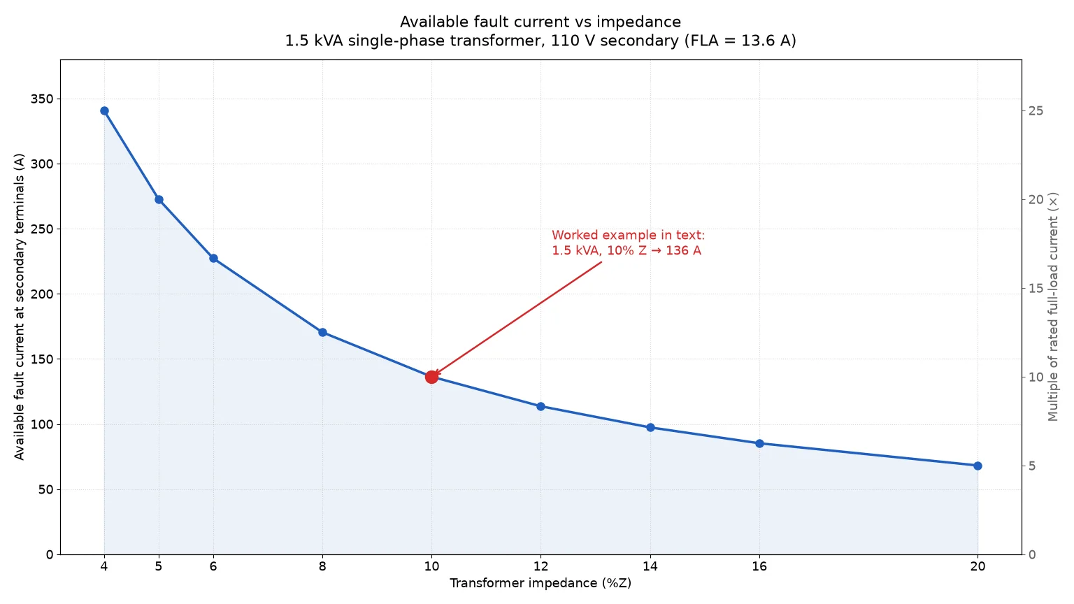
That is the whole calculation: roughly 136 amps available at the secondary terminals, about ten times rated current — a figure an ordinary 10 kA-rated miniature breaker interrupts without breaking a sweat. On a machine this size the fault current swings dramatically with the assumed impedance, which is why step 2 deserves more attention than it usually gets. The chart below shows the same transformer at different impedance values — 340 A at 4% impedance, only 68 A at 20%.
Typical Fault Currents on Small Dry-Type Transformers
Small transformers have comparatively high impedance. Winding conductors are thin and the leakage path between primary and secondary is short, so %Z sits well above the 4–6% typical of large distribution units. Design ranges for common single-phase sizes, at a 110 V secondary:
| Transformatörün nominal değeri |
Typical %Z range |
Rated secondary current |
Estimated fault current (at 10% Z) |
| 1 kVA |
12–20% |
9.1 A |
≈ 91 A |
| 1.5 kVA |
8–15% |
13.6 A |
≈ 136 A |
| 3 kVA |
7–13% |
27.3 A |
≈ 273 A |
| 5 kVA |
6–12% |
45.5 A |
≈ 455 A |
| 10 kVA |
5–10% |
90.9 A |
≈ 909 A |
Typical design ranges, not nameplate data — confirm the exact value of any given unit with the manufacturer or by measurement. Fault-current column assumes 10% for comparability.
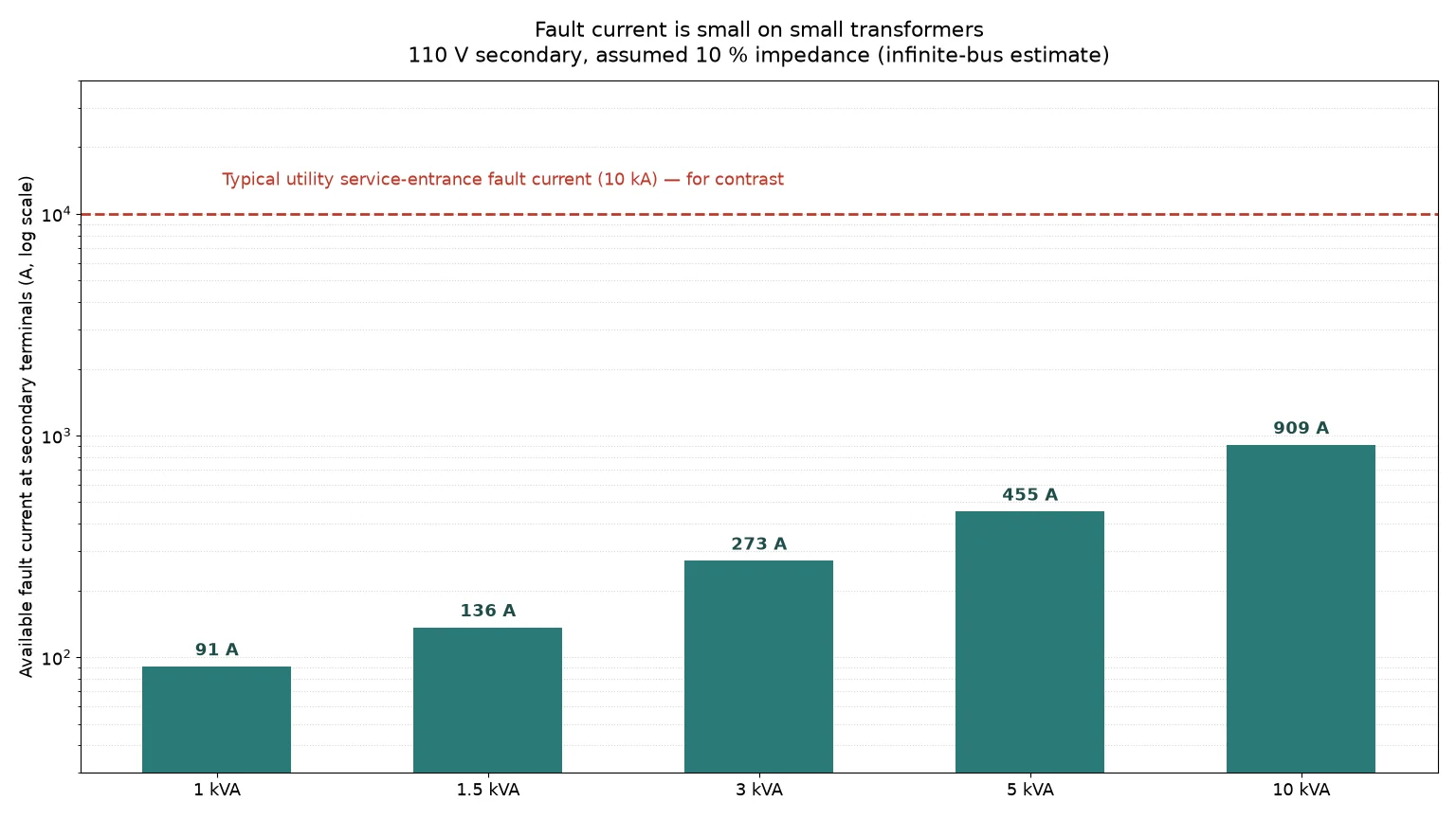
Even the largest machine in the table delivers under a kiloampere at its terminals — roughly a tenth of the fault level at a typical utility service entrance. On small transformers, the fault-current question is therefore almost never “will my breaker survive?” It is “will my protection scheme protect the windings, and will it hold through inrush without nuisance-tripping?” The chart below puts the two scales side by side.
How Accurate Is the Infinite-Bus Assumption Here?
For large transformers the infinite-bus assumption can be badly wrong: a 1,500 kVA unit that delivers 31 kA by itself is materially limited by the utility feed’s impedance. On small transformers the situation reverses, and the textbook assumption becomes almost exact.
The reason is proportionality. A service entrance capable of 10 kA has an effective source impedance of a few hundredths of an ohm at 110 V, while the 1.5 kVA transformer at 10% impedance presents about 0.8 Ω to the secondary. The source impedance is under 1% of the total, so ignoring it costs almost nothing in accuracy. What does matter is what you add between the transformer and the fault point: a few meters of secondary cable can shave 10–20% off the value at the far end. The practical habit is simple — calculate the worst case at the terminals, and account for the cable run only if a downstream device sits close to its interrupting rating, which at these levels is rare.
When the exact value matters — for a coordination study, or when comparing quotes — measure it with the classic short-circuit test: short the secondary, apply a reduced voltage on the primary until rated current flows, and %Z equals applied voltage divided by rated voltage. The same bench technique underlies our guide on measuring DC resistance of transformer windings, which pairs naturally with the impedance test when characterizing a unit.
Transformer Protection: What Actually Matters on a Small Unit
With fault currents in the tens or hundreds of amps, equipment withstand is a non-issue, and protection design reduces to three decisions.
1. Primary overcurrent protection. Small transformers are protected from the primary side in almost all installations. Standards such as NEC Table 450.3(B) allow primary-only protection sized no more than 125% of rated primary current, with a next-higher standard device rating permitted where 125% does not correspond to a standard size. For the 1.5 kVA example, rated primary current at 220 V is about 6.8 A, which puts you in the 8–10 A range. The current rating, however, is not the hard part:
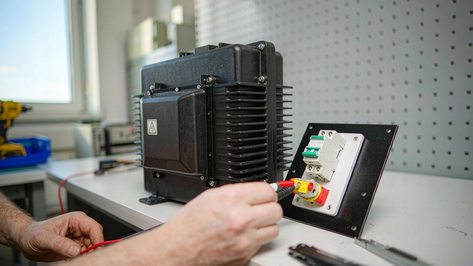
2. Surviving magnetizing inrush. This decision separates a working installation from a support-ticket generator. When a transformer is energized, the core can momentarily saturate and draw an inrush of 8 to 30 times rated current for the first few cycles — on small cores, often more than the worst-case fault current. Inrush is değil fault current: it decays within a fraction of a second and is harmless to the windings. But a fast magnetic breaker or fast-acting fuse cannot tell the difference, trips on every power-up, and the installer blames the transformer. The fixes are standard practice: a time-delay (slow-blow) fuse or a C- or D-curve breaker on the primary, switching the primary rather than the secondary, and a soft-start for repeatedly-switched loads. Our article on what causes a transformer to blow covers the failure modes that follow when this step is skipped.
3. Secondary protection against overload. The uncomfortable truth about small transformers: the fault current you just calculated protects nothing. A 136 A bolted-fault capability does not prevent the winding from cooking slowly at 20 A of continuous overload — and overload, not short circuit, is the everyday enemy of a 100 VA to 10 kVA dry-type unit. If the load can realistically draw more than rated current (machine tools, motors, anything with a stalled-rotor condition), add secondary overcurrent protection at or below 125% of rated secondary current: about 15 A for this example. Watch the voltage-regulation trade-off while you do — impedance that limits fault current also causes voltage dip under load, as explained in our article on transformer voltage regulation.
| Decision |
Rule of thumb |
1.5 kVA / 220 V example |
| Primary protection rating |
≤ 125% of rated primary current, time-delay characteristic |
~6.8 A rated → 8–10 A slow fuse or C-curve MCB |
| Inrush withstand |
Time-delay fuse or C/D-curve breaker; switch the primary side |
Inrush 55–200 A for 1–2 cycles — device must not trip |
| Secondary protection |
≤ 125% of rated secondary current if overload is possible |
~13.6 A rated → 15 A max |
| Interrupting rating |
≥ available fault current at that point |
136 A ≪ 10 kA MCB rating — automatically satisfied |
| Thermal margin |
Keep continuous load ≤ 80% of rating |
≤ ~12 A continuous on the 110 V winding (13.6 A rated) |
One last note on honesty in the numbers: the %Z values above are typical design ranges, and any specific unit — including our own DT series, such as the 1.5 kVA step-up and step-down transformer used in the worked example — should be confirmed against its datasheet or measured on the bench when the calculation feeds a formal coordination study.
SSS
Is available fault current the same as short-circuit current?
Available fault current is the maximum short-circuit current the supply can deliver at a point — the bolted-fault, worst-case value. The terms are used interchangeably, but “available” emphasizes it is a property of the supply at that location, not of any device connected there.
Where do I find %Z on a small transformer?
You often won’t — nameplates on 100 VA to 10 kVA dry-type units commonly omit it. Estimate from typical ranges (8–15% for a 1.5 kVA unit), or measure it with the short-circuit test described above.
Does a higher impedance transformer reduce fault current?
Yes, linearly. Doubling %Z halves the available fault current — good for equipment withstand, but the same impedance causes more voltage drop under load, for the same physical reason.
Why does my transformer breaker trip at power-up with no load?
Almost certainly magnetizing inrush, not a fault. Energizing a transformer can draw 8–30 times rated current for the first few cycles. Replace a fast breaker with a time-delay fuse or a C-curve breaker, and switch the primary rather than the secondary.
Can I use these formulas on three-phase transformers?
Yes — use FLA = kVA × 1000 / (√3 × V) and the same Isc = FLA × 100 / %Z. Everything else in this article, including the inrush behavior and the protection checklist, carries over unchanged.
Sonuç
The available fault current at a transformer secondary is a one-line calculation — full-load current divided by per-unit impedance — but on small dry-type transformers the result reorders your priorities. Interrupting ratings that dominate large-transformer design are satisfied automatically at hundreds of amps, and the protection problems that actually bite are inrush coordination on the primary and overload protection on the secondary. Compute the worst case with the infinite-bus formula, sanity-check it against the impedance you measure or confirm with the manufacturer, and size the devices around the transformer’s thermal limits rather than its fault capability.
If you are specifying a small step-up or step-down transformer and want the impedance and protection data for your coordination study, mühendislik ekibimizle iletişime geçin — we support custom voltages and kVA sizes from 100 VA upward.