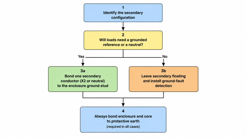
A transformer isolates its output electrically, but isolation is not the same as safety. If you leave the secondary winding floating, the whole low-voltage circuit drifts to an undefined potential relative to earth — and a single insulation fault inside the unit can pull the entire output up toward primary voltage. Correct transformer grounding solves this with two separate connections: bond the metal enclosure and core to protective earth, and bond one conductor of the secondary winding to that same earth point. The first connection protects people from a live chassis. The second gives the output circuit a stable voltage reference and gives your breakers and fuses a fault path they can actually clear.
This guide covers how to ground the secondary of small dry-type yükseltici ve düşürücü transformatörler in the 100 VA to 10 kVA range — the units that power machine control panels, HVAC equipment, and imported appliances. The wiring logic below applies in both NEC and IEC markets; always confirm the local code edition before energizing.
What Grounding the Secondary Actually Does
Grounding the secondary winding does three jobs at once, and it helps to keep them separate in your head:
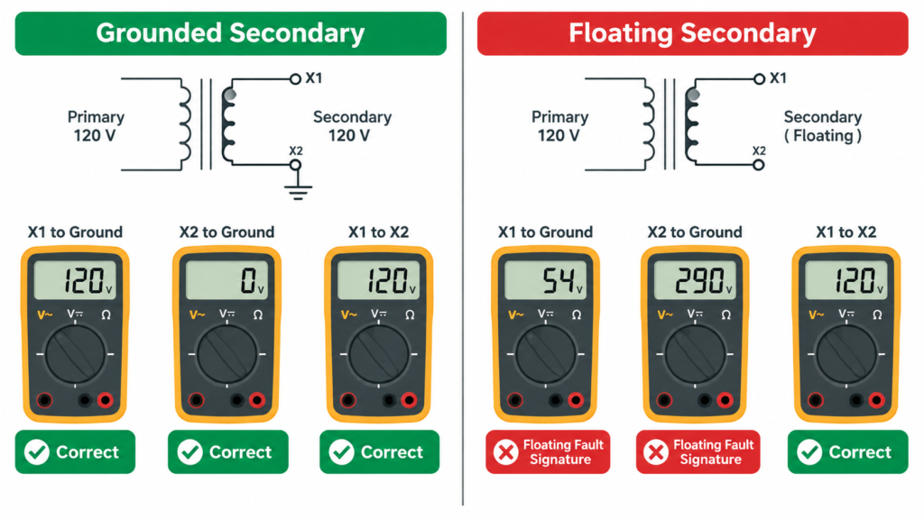
It fixes the voltage reference. A grounded secondary holds each output conductor at a predictable potential to earth. Without that bond, stray capacitance between windings and the grounded enclosure forms a voltage divider, and readings drift to meaningless values — 50 V here, 290 V there — even though the winding itself is healthy.
It creates a fault-clearing path. When a secondary conductor shorts to the frame, the fault current flows through the bonding jumper and back to the source, quickly tripping the protective device. On a floating system, that first fault draws almost no current, nothing trips, and the fault sits there waiting for a second one.
It limits touch voltage. If the primary insulation fails, a grounded secondary prevents the high-voltage side from raising the low-voltage circuit above a dangerous potential.
Note what is değil on that list: grounding the secondary does not replace grounding the enclosure. Correct transformer grounding always includes both connections, and confusing them is one of the most common installation errors.
Which Secondary Conductor Should You Ground?
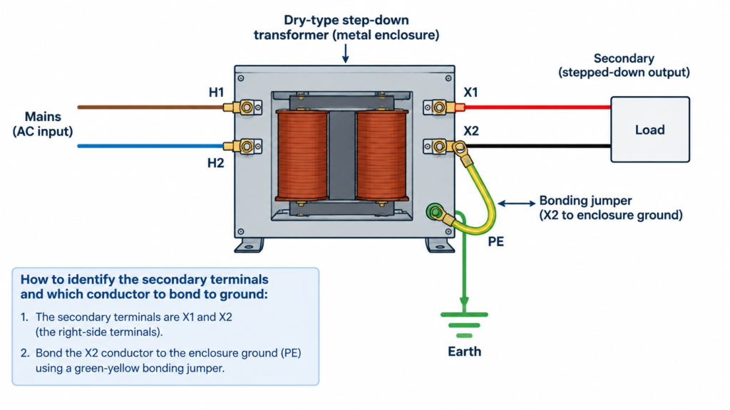
On a two-wire single-phase secondary, the answer is simple: ground one conductor, and by convention it is the one you intend to use as the grounded circuit conductor — terminal X2 on most dry-type units. On a center-tapped or multi-voltage secondary, ground the center tap or the neutral terminal instead. The table below maps the common cases:
Secondary configuration
Ground this point
Why
Two-wire single-phase (X1–X2)
X2
Creates a grounded conductor for the output circuit; X1 becomes the “hot” leg
Center-tapped (120/240 V style)
Center tap / neutral
Splits the output into two balanced halves and limits voltage to ground
Three-phase wye with neutral (X0)
X0
Defines the neutral and lets single-phase loads connect line-to-neutral
Three-phase delta, no neutral
One phase (corner-grounded) — or none, with ground-fault detection
A delta has no neutral point; corner grounding is one option where code allows
Before you bond anything, confirm which terminal is which. Terminal identification on small transformers follows the same logic as identifying line and neutral conductors in the rest of the installation, and if you need a refresher, our guide on transformer live wire and neutral wire identification walks through it terminal by terminal. For a wye-connected three-phase secondary, the same principle extends directly — see our Üç fazlı transformatör bağlantı talimatları for the full terminal layout.
Step-by-Step: Grounding the Secondary the Right Way
The sequence below assumes a de-energized, lockout-tagged unit. Do not skip step 1.
De-energize and verify. Lock out the primary feeder, then confirm zero voltage at every terminal with a meter you have just proven on a known live source.
Identify the secondary terminals. Read the nameplate and wiring diagram. X terminals are secondary; H terminals are primary. If the unit has multiple secondary voltages, decide which winding configuration you are using before touching a screw.
Bond the enclosure and core first. Run an equipment grounding conductor from the enclosure ground stud or lug to the grounding electrode system. Many dry-type transformers provide a dedicated ground stud on the chassis — use it, and scrape any paint from the contact surface so the connection is metal-to-metal.
Install the bonding jumper. Run a copper bonding jumper from the selected secondary terminal (X2 in a two-wire system) to the same ground stud. Size it at least as large as the secondary phase conductors; undersized jumpers melt before the breaker clears the fault.
Keep the bond single-point. The secondary neutral-to-ground bond must exist at the transformer only. Downstream panels and loads must never re-bond neutral to ground, or fault current will split between paths and nuisance-trip or fail to trip.
Label and document. Mark the grounded conductor, record the bonding configuration on the panel schedule, and keep the wiring diagram with the installation records for the next technician.
If the load genuinely needs an ungrounded secondary — some test benches and medical equipment do — that is a design decision, not an oversight. In that case the system needs ground-fault detection that alarms on the first fault, per NEC 250.21 or the equivalent IEC provision. What you cannot do is simply leave it floating and hope.
The Step-Up Case: When the Secondary Is the High Side
Step-up transformers introduce a wrinkle that the code guides rarely spell out: the “secondary” here is the higher-voltage winding. A 110 V to 220 V unit stepping up for imported equipment, for example, outputs 220 V between two secondary terminals with no neutral brought out. You still ground one leg of that secondary to establish a reference — but understand the consequence first. Once you corner-ground it, every point of the output circuit sits at up to full line voltage relative to earth, and a person touching the “neutral” side of a 220 V load can receive a shock that a floating system would not have produced.
For small step-up/step-down units feeding portable or plug-connected loads with their own double insulation, many manufacturers leave the secondary floating and rely on the isolation boundary plus the enclosure bond. For permanently wired installations feeding distribution panels, most codes expect the secondary grounded as a separately derived system. Check the equipment’s listing and the local code before choosing; when the two conflict, the stricter requirement wins.
How to Verify the Ground with Voltage Readings
Before energizing, measure the resistance between the bonded secondary terminal and the enclosure ground stud — it should read well below one ohm. After energizing, the voltage-to-ground measurements tell you immediately whether the bond is doing its job:
Measurement (120 V example)
Grounded secondary
Floating secondary
X1 to ground
≈ 120 V
Unstable, often 50–80 V
X2 to ground
≈ 0 V
Unstable, can exceed 200 V
X1 to X2
120 V
120 V (winding is fine)
The giveaway is the third row: when X1 to X2 reads correctly but the ground-referenced values are nonsense, the winding is healthy and the bond is missing. That 290 V phantom reading people report on floating secondaries comes from capacitive coupling through the windings and wiring — it is real voltage on a high-impedance meter and it can still deliver a shock. Clamp the equipment grounding conductor during commissioning too: any current flowing in it means a fault or a second neutral-to-ground bond somewhere downstream. These checks pair naturally with the pre-energization tests in our transformer turns ratio test guide, which verifies the winding itself before you close up the panel.
Five Grounding Mistakes That Show Up in the Field
Grounding only the enclosure. The chassis is safe, but the output circuit still floats — every control board and sensor connected to it sees undefined potentials to earth.
Bonding neutral to ground twice. A second bond in a downstream panel creates parallel paths, divides fault current, and makes ground-fault protection unreliable.
Using the protective earth conductor as the return path. The green or green-yellow wire must carry current only during a fault. Current in it during normal operation means miswiring.
Undersizing the bonding jumper. The jumper must survive long enough to trip the protective device. Match it to the secondary conductor size, not to “whatever wire is on the shelf.”
Skipping the enclosure bond on plastic-housed mounts. Even when the transformer sits on an insulated bracket, the core, frame, and any metallic housing still need a bond to earth.
Sık Sorulan Sorular
What happens if you don’t ground a transformer secondary?
The output floats at an undefined potential, voltage-to-ground readings become unpredictable, and a single ground fault trips nothing. The first fault often goes unnoticed until a second fault — or an insulation failure — turns it into a short circuit or a shock hazard.
Should you ground both X1 and X2?
No. Grounding both terminals creates a dead short through the grounding system the moment the transformer energizes. Ground exactly one conductor, plus the enclosure.
Does the secondary of a step-up transformer need grounding?
For permanently installed systems feeding a panel, yes — it is a separately derived system and one secondary conductor must be bonded to earth. For small units feeding plug-connected, double-insulated equipment, a floating secondary is common practice, but the enclosure itself must always be grounded.
What size bonding jumper do I need?
Match or exceed the secondary phase conductor size, and follow the code table for your jurisdiction (NEC Table 250.102(C)(1) is the common NEC reference). On a 1.5 kVA unit with 14 AWG secondary wiring, a 14 AWG copper jumper is the minimum; heavier gauge costs little and adds margin.
Get the Grounding Right Before the First Fault
Transformer grounding comes down to two connections and one discipline: bond the enclosure to earth, bond one secondary conductor to earth, and do it at a single point. The five-minute resistance check and the voltage-to-ground readings after energizing will tell you whether the installation matches the drawing. If you are selecting a transformer for a new installation, the DT-1500VA yükseltici ve alçaltıcı transformatör and its series mates ship with clearly marked H/X terminals and a chassis ground stud that makes the bonding work straightforward — and our team can advise on grounding configurations for specific projects.
İspanya için 230 V - 110 V transformatör: REBT uyumluluğu, ITC-BT-18 ve ITC-BT-24 standartları, ikincil devrenin topraklanması ve UNE-EN IEC 61558 belgeleri.
Hollanda için 230 V - 110 V transformatör: NEN 1010, 30 mA kaçak akım kuralları, kaçak akım anahtarı ile otomatik kaçak akım şalteri arasındaki fark ve ikincil topraklama.