Oto-transformatör Devrelerinin Kablolama Yöntemi: Adım Adım Kılavuz
Yayın tarihi: Yazar: Lisa
Wiring an ototransformatör circuit is simpler than wiring a conventional two-winding transformer, but it requires careful attention to terminal identification and tap selection. Whether you are setting up a step-down unit for imported equipment, configuring a step-up connection for industrial machinery, or wiring a variable autotransformer for a test bench, getting the connections right keeps your equipment safe and your voltage stable. This guide walks you through the most common autotransformer circuits wiring configurations with clear, practical instructions.
How Autotransformer Circuits Differ from Conventional Transformer Circuits
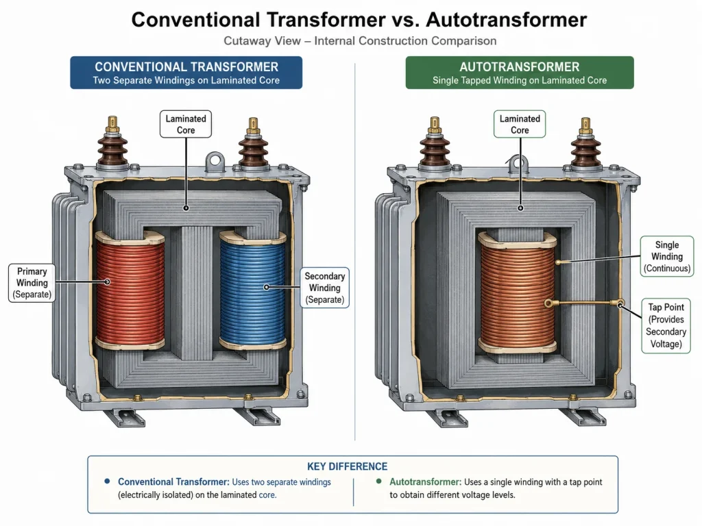
Before connecting any wires, it helps to understand what makes an autotransformer circuits different. A conventional transformer has two electrically isolated windings: a primary and a secondary. An autotransformer uses a tek parça kesintisiz sargı with one or more tap points. Part of the winding serves as both the primary and the secondary, which is why the device is smaller, lighter, and more efficient than an equivalent two-winding transformer.
This shared-winding design means the input and output sides share a common electrical connection. There is no galvanic isolation between them, which has important safety implications we will cover later. If you need a refresher on autotransformer theory before wiring, see our guide on what an autotransformer is and how it works.
Understanding Autotransformer Terminal Markings
Reading terminal labels correctly is the first step in wiring any autotransformer circuit. Manufacturers use different labeling conventions, but most follow either ANSI veya IEC standards. Common markings you will encounter:
Marking Style
Common Terminal
Input (Primary)
Output (Secondary)
IEC standard
0 or COM
U1, V1 or L1
U2, V2 or L2
ANSI standard
C or COM
H1, H2
X1, X2
Generic/Small units
0V, GND, or COM
220V, 230V, 240V
110V, 115V, 120V
Variable units (Variac)
Terminal 2 or C
Terminals 1 and 2
Terminals 2 and 3
Always check the nameplate diagram on your unit before making connections. Terminal positions vary by manufacturer, and assuming a standard layout can lead to wiring errors. Refer to our autotransformer symbol and diagram guide for detailed explanations of standard notation.
How to Wire a Step-Down Autotransformer Circuits
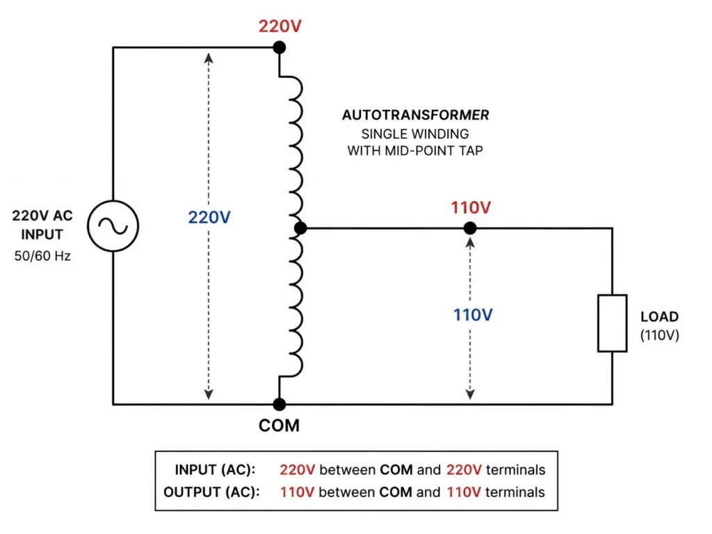
A step-down autotransformer takes a higher input voltage and delivers a lower output voltage. The most common residential and commercial configuration converts 220V - 110V veya 230V to 115V for imported equipment.
Wiring Steps for Single-Phase Step-Down (e.g., 220V to 110V)
Identify the common terminal (typically marked COM, 0, or C). This terminal is shared by both input and output.
Identify the 220V terminal (sometimes marked H1, L, or the full-winding endpoint). This is where you connect one side of the input supply.
Identify the 110V tap (sometimes marked X1, 110V, or the mid-point tap). This is your output hot terminal.
Connect input: Wire the incoming 220V supply lines to the common terminal and the 220V terminal.
Connect output: Wire your load between the common terminal and the 110V tap. The common terminal serves as the neutral or return for both sides.
Ground the enclosure: Connect the grounding lug on the transformer chassis to your building’s ground system using appropriately sized green or bare copper wire.
Size the overcurrent protection: Install a circuit breaker or fuse on the input side rated for the transformer’s rated primary current.
In this configuration, the full winding receives the 220V input, while the output is taken from a tap at the midpoint. Current flows through the common section by conduction, not just induction — this is what makes the autotransformer more efficient than a conventional step-down transformer.
How to Wire a Step-Up Autotransformer Circuits
A step-up autotransformer circuit increases voltage from a lower input to a higher output. Common uses include running 110V equipment from a 220V source, powering industrial controls that require 480V from a 240V feed, or matching equipment to regional grid voltages.
Wiring Steps for Single-Phase Step-Up (e.g., 110V to 220V)
Identify the common terminal (COM, 0, or C). This is shared by both input and output.
Identify the 110V tap — this is where input power is connected.
Identify the 220V terminal — the full-winding endpoint that delivers the stepped-up output.
Connect input: Wire the incoming 110V supply to the common terminal and the 110V tap.
Connect output: Wire your load between the common terminal and the 220V terminal.
Ground and protect: As with step-down wiring, connect the chassis ground and install input-side overcurrent protection.
The key difference from step-down wiring is where you connect the input. In step-up mode, the input feeds only a portion of the winding, and the output spans the full winding. The voltage ratio follows the turns ratio: if the 110V tap is at the midpoint of a 220V winding, the output is exactly double the input.
If you need both step-up and step-down capability, consider a multi-tap unit. Our step-up and step-down transformer product range includes models with selectable input/output taps that support multiple voltage combinations from a single device.
How to Wire a Variable Autotransformer (Variac)
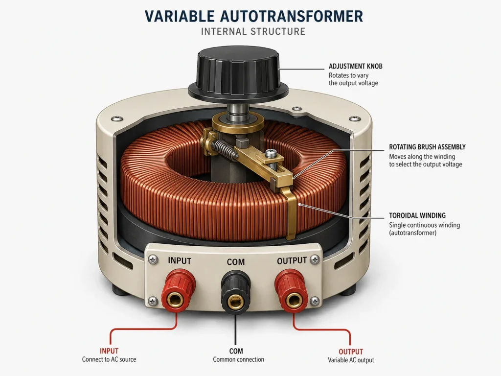
Variable autotransformers, commonly known as Variacs or variable AC transformers, use a rotating brush that slides along an exposed winding. This allows you to continuously adjust output voltage from zero to above the input level. They are a staple in testing labs, dimmer applications, and repair shops.
Wiring Steps for a Variable Autotransformer
Locate the input terminals: Most variable autotransformers have three or four terminals. Two are for the fixed AC input. Common labels: terminals 1 and 4 for input, or terminals marked AC IN.
Locate the output terminals: The variable output is typically taken from the common terminal and the brush terminal (often terminal 2 or marked OUT).
Connect input: Wire your AC supply to the designated input terminals. On a typical 4-terminal unit, connect line to terminal 1 and neutral to terminal 4.
Connect output: Wire your load to terminal 1 (common) and terminal 2 (brush/output).
Confirm rotation range: Before connecting a load, power the unit and turn the knob from zero to maximum while measuring output voltage with a multimeter. Verify the full range matches your needs.
Install a fuse on the output side: Because the brush makes sliding contact, an output fuse protects against short-circuit conditions at low voltage settings where winding current could otherwise exceed safe limits.
Variable autotransformers do not isolate the output from the input mains. Always treat the output as live with respect to ground. For test bench setups that require isolation, use a separate isolation transformer upstream.
How to Wire a Three-Phase Autotransformer Circuits
Three-phase autotransformers wire similarly to single-phase units, but across three identical winding sections. The two most common configurations are Wye (Star) ve Delta connections, each with its own terminal layout.
Wye (Star) Connection
Each phase winding has a common neutral point connected together.
Input phases L1, L2, L3 connect to the full-winding endpoints of each phase winding.
Output is taken from tap points on each phase winding — typically at the same percentage for balanced output.
The common neutral may or may not be brought out. On a 4-wire system, the neutral connects to the common point.
Delta Connection
The three phase windings are connected in a closed loop (end of one winding to the start of the next).
Input phases connect to the three corners of the delta.
Output is taken from tap points within each winding leg.
Delta configurations have no neutral point. They are common in industrial motor-starting applications where balanced three-phase loads are the norm.
Always verify the vector group on the nameplate. Connecting a wye-configured transformer into a delta system (or vice versa) can cause severe voltage imbalance and equipment damage. Three-phase wiring requires careful phase sequencing; use a phase rotation meter to confirm correct L1-L2-L3 order before energizing the load.
Common Autotransformer Wiring Mistakes and How to Avoid Them
Hata
What Happens
Nasıl Önlenir?
Reversing input and output
Step-down unit connected backward delivers dangerously high voltage; step-up unit produces insufficient voltage
Always check the nameplate for input/output labels before connecting
Using the wrong tap
Incorrect output voltage damages connected equipment
Verify tap voltage with a multimeter before connecting the load
Omitting overcurrent protection
Winding damage or fire in the event of a short circuit or overload
Install a properly sized breaker or fuse on the input side
Forgetting the ground connection
Exposed metal parts can become live during a fault, creating an electrocution hazard
Connect the chassis ground lug to the building ground with appropriate wire gauge
Assuming galvanic isolation
Shock hazard when touching the “output” side, which is electrically common with the mains input
Treat both input and output as live circuits; never assume isolation
Undersizing wiring for the current
Overheated conductors, voltage drop, and potential fire risk
Calculate full-load current and select wire gauge per local electrical code
Testing Your Autotransformer Circuits After Wiring
Before powering your load, run through this quick checklist to confirm a safe and correct installation:
Visual inspection: Confirm all terminals are tight, no stray wire strands are touching adjacent terminals, and all connections match the wiring diagram.
Continuity check (power off): Using a multimeter, verify the common terminal has continuity to both the input and output hot terminals. This confirms the shared-winding nature of the autotransformer.
No-load voltage test: With the output disconnected from the load, energize the input and measure the output voltage. It should match the expected value within a few percent.
Load test: Connect a small, known-good load and measure output voltage under load. Any significant drop may indicate undersized wiring, a poor connection, or an undersized transformer.
Enclosure temperature check: Run the transformer under load for 15-30 minutes, then check the enclosure for any unexpected hot spots.
Choosing the Right Autotransformer for Your Wiring Project
Before wiring, make sure you have the right unit. Three factors matter most:
kVA rating: Total load power plus 20-25% headroom for inrush and future expansion.
Voltage range: Input voltage must match your supply; output tap must match your load requirements.
Muhafaza türü: Indoor (NEMA 1/IP20), outdoor (NEMA 3R/IP54), or open-frame for panel mounting.
Can I wire an autotransformer for both step-up and step-down?
Yes, many autotransformers are designed as dual-voltage units with multiple taps. By connecting the input and output to different tap combinations, the same unit can step voltage up or down. However, the nameplate must explicitly indicate dual-mode capability. If you need this flexibility, a multi-tap model is the right choice.
Do I need a neutral connection for an autotransformer circuits?
For single-phase autotransformer circuits, the common terminal serves the role of the neutral in most 2-wire-plus-ground installations. In three-phase wye configurations, a neutral may be brought out from the common star point. Delta configurations have no neutral connection.
What wire gauge should I use for autotransformer connections?
Wire gauge depends on the rated current of the circuit. Calculate the full-load current by dividing the kVA rating by the operating voltage, then select wire gauge per your local electrical code (NEC in North America, IEC 60364 internationally). For example, a 5kVA autotransformer at 220V input draws about 23A, requiring at least 10 AWG (or 4 mm²) copper wire.
Can I use an autotransformer with DC voltage?
No. Autotransformers rely on electromagnetic induction, which requires a time-varying magnetic field. They only work with alternating current (AC). Applying DC will saturate the core and potentially burn out the winding.
Why does my autotransformer hum after wiring?
A mild 50/60 Hz hum is normal and comes from manyetostriksiyon in the iron core. If the hum is unusually loud, check for loose mounting bolts, an overloaded transformer, or a DC offset on the supply line. Tightening the core bolts and mounting brackets often reduces audible noise.
How do I protect an autotransformer circuits from short circuits?
Autotransformers have lower internal impedance than equivalent two-winding transformers, meaning short-circuit currents can be several times higher. Install a properly rated circuit breaker or fuse on the input side, and consider adding output-side protection for valuable loads. The lower impedance is an inherent trade-off of the compact design — learn why in our comparison of autotransformers and conventional transformers.
İspanya için 230 V - 110 V transformatör: REBT uyumluluğu, ITC-BT-18 ve ITC-BT-24 standartları, ikincil devrenin topraklanması ve UNE-EN IEC 61558 belgeleri.
Hollanda için 230 V - 110 V transformatör: NEN 1010, 30 mA kaçak akım kuralları, kaçak akım anahtarı ile otomatik kaçak akım şalteri arasındaki fark ve ikincil topraklama.