Bộ chuyển đổi dòng điện sang điện áp hoạt động như thế nào?
Ngày đăng: Tác giả: Lisa
A current to voltage converter turns an input current into a proportional output voltage. In signal-conditioning circuits, it is usually called a transimpedance amplifier, or TIA. The most common design uses an operational amplifier and a feedback resistor so that even a very small sensor current can become a voltage that an analog-to-digital converter, meter, controller, or oscilloscope can read.
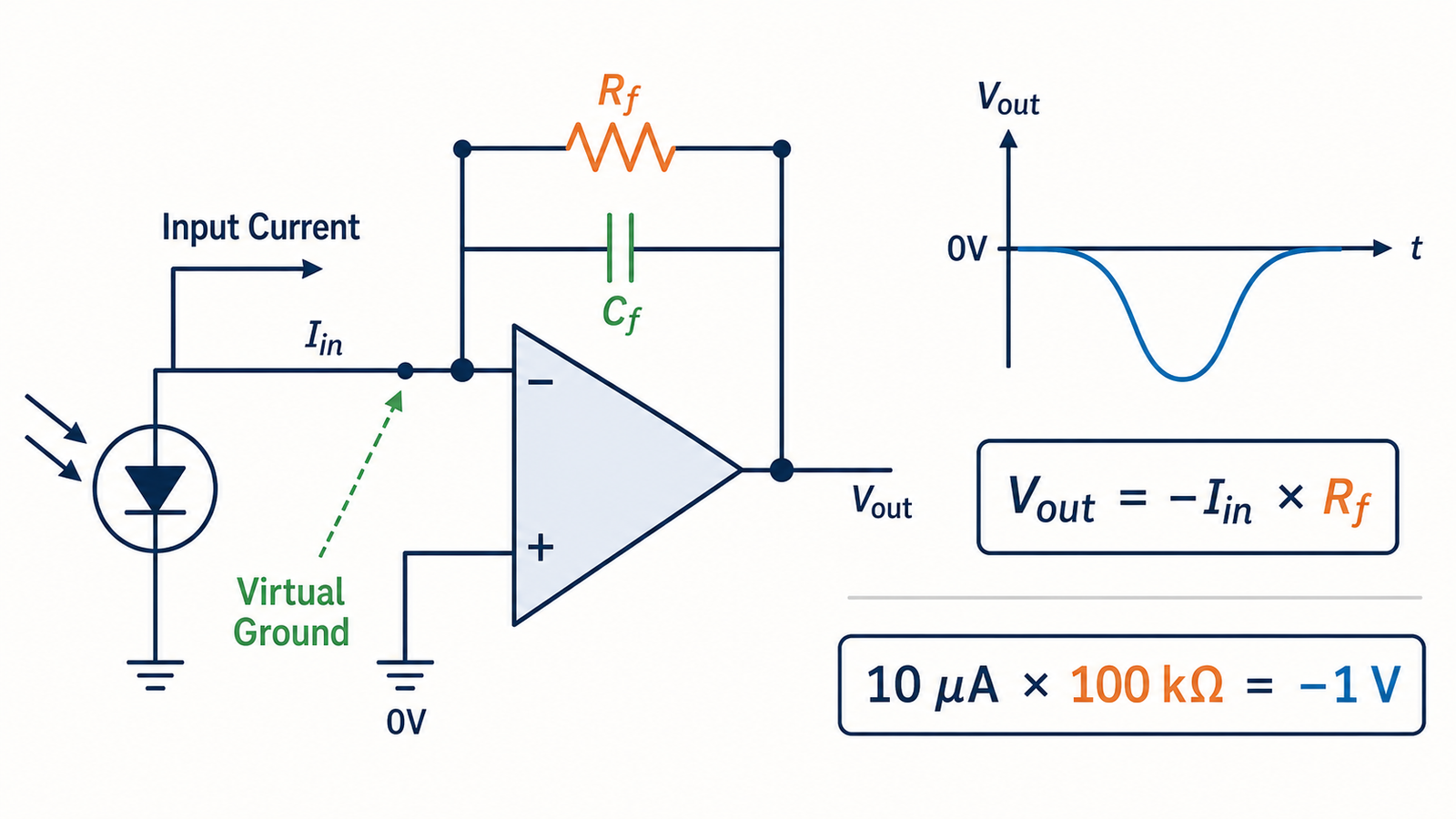
The basic relationship is simple: the input current flows through the feedback impedance, and the amplifier adjusts its output to hold the input node at an almost constant reference voltage. For the standard inverting circuit, the ideal result is Vra = −Itrong × Rf. The rest of the design is about selecting gain, bandwidth, noise, stability, and voltage range correctly.
What Is a Current to Voltage Converter?
A current to voltage converter is a signal-conditioning circuit whose output voltage represents the magnitude and direction of an input current. The ratio between output voltage and input current has units of ohms and is called transimpedance. A feedback resistance of 100 kΩ, for example, gives an ideal sensitivity of 100,000 volts per ampere, or 0.1 volt per microampere.
This electronic meaning should not be confused with a mains voltage transformer. A TIA processes low-level signals from sensors and measurement circuits. A power transformer changes AC voltage for equipment and provides power at a useful voltage level. Both involve electrical conversion, but they solve different engineering problems and are specified in different ways.
Bộ chuyển đổi dòng điện sang điện áp hoạt động như thế nào?
1. The source generates an input current
The source may be a photodiode, photomultiplier, electrochemical sensor, current transformer interface, or another transducer. Instead of producing a convenient voltage, it produces a current related to light, radiation, chemical concentration, magnetic field, or another measured quantity.
2. The op-amp maintains a virtual reference node
In a typical inverting TIA, the non-inverting input is connected to ground or another reference voltage. Negative feedback makes the op-amp drive its output until the inverting input sits very close to that same voltage. Engineers call this point a virtual ground when the reference is 0V. It is not physically connected to ground, but feedback keeps it near ground potential during normal linear operation.
3. Input current flows through the feedback resistor
An ideal op-amp input draws no current. Therefore, almost all current from the source must flow through the feedback resistor Rf. The op-amp produces whatever output voltage is required to support that current through the resistor. If current flows into the inverting input, the output moves negative; if the current direction reverses, the output moves positive.
Ideal transfer equation: Vra = Vtham chiếu − ItrongRf
With a 10 µA input, a 100 kΩ feedback resistor, and a 0V reference, the ideal output is −1V. Changing Rf to 1 MΩ raises the sensitivity to −10V for the same current, but it also affects noise, bandwidth, and output range.
4. A feedback capacitor controls bandwidth and stability
Real sensors and op-amp inputs have capacitance. Combined with a large feedback resistance, that capacitance can create excessive gain peaking or oscillation. Designers often place a small capacitor Cf in parallel with Rf. This limits high-frequency gain and stabilizes the circuit, but too much capacitance slows the response. The correct value depends on source capacitance, op-amp gain-bandwidth product, noise gain, and the required signal bandwidth.
Resistor Conversion vs. an Op-Amp TIA
Ohm’s law means a resistor alone can convert current into voltage: V = I × R. However, the voltage developed across a passive sense resistor can change the source operating point. That loading error is especially important with photodiodes and other high-impedance or low-current sources.
Tính năng
Sense resistor only
Op-amp transimpedance amplifier
Complexity
Rất thấp
Requires op-amp, supply, and feedback parts
Input node voltage
Changes with current
Held near a reference voltage
Sensor loading
Can be significant
Usually much lower
Output drive
Limited by the source
Driven by the op-amp
Precision and gain
Good for simple current sensing
Better for small signals and controlled gain
A shunt resistor is often suitable for measuring moderate power-supply or motor current when a small voltage drop is acceptable. A TIA is usually better when the source current is tiny, source loading must remain low, or the measurement needs a buffered output.
How to Select the Feedback Resistor
Begin with the largest expected input current and the usable output swing of the op-amp. The first-pass value is:
Rf = desired output change ÷ maximum input current
Suppose a sensor produces 0–20 µA and the desired output change is 0–4V. The ideal feedback resistance is 200 kΩ. Choose a standard precision value, then confirm that the op-amp can reach the required output voltage under the intended supply and load. Leave margin from the supply rails and account for current direction.
A larger resistor increases volts-per-amp sensitivity, but it also increases resistor thermal noise and usually reduces bandwidth. For a very wide current range, selectable feedback resistors or multiple gain channels can give better resolution than one extremely large resistor.
Important Design Limits
Output saturation: if I trong R f demands more voltage than the op-amp can produce, the output clips and the virtual-ground assumption fails.
Input bias current: op-amp input current creates an offset that can be large relative to nanoampere or picoampere sensor signals.
Offset voltage: input offset appears as output error through the circuit’s noise gain.
Noise: sensor noise, op-amp current and voltage noise, resistor thermal noise, and external interference all affect resolution.
Bandwidth: higher transimpedance gain generally makes wide bandwidth more difficult.
Input capacitance: photodiode, cable, PCB, and op-amp capacitances influence stability.
Common-mode and supply range: the selected op-amp must operate correctly at the reference input voltage and required output swing.
Common Current to Voltage Converter Applications
Photodiode and optical sensing
Photodiodes generate current proportional to incident light. A TIA keeps the photodiode terminal voltage controlled while converting photocurrent into a voltage for measurement. Applications include optical receivers, light meters, spectroscopy, smoke detection, and industrial optical sensors.
Industrial 4–20mA signal reception
A receiver can pass a 4–20mA loop signal through a precision resistor to produce a voltage such as 1–5V. Depending on isolation, grounding, accuracy, and protection requirements, the design may also use buffering, differential amplification, surge protection, or an isolated signal conditioner.
Current transformer measurement
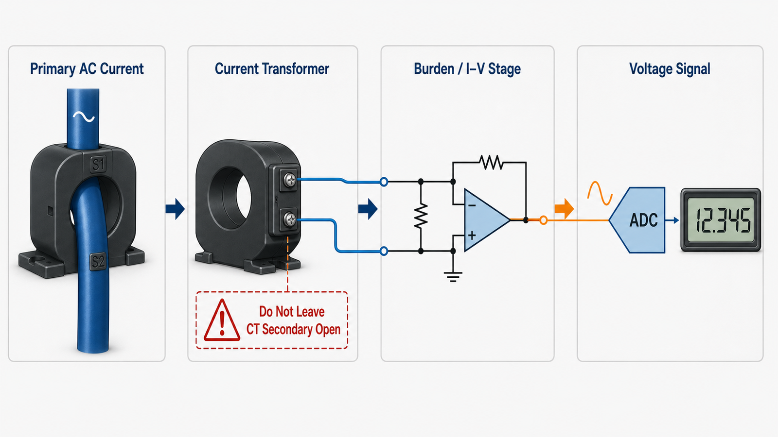
A current transformer produces a secondary current proportional to primary AC current. A burden resistor or active current-to-voltage front end converts that current into a voltage for metering or protection electronics. Current transformers must be used according to their manufacturer’s safety instructions; an energized CT secondary should not be left open when the design requires a burden.
DAC and precision instrumentation
Some digital-to-analog converters provide a current output. An op-amp I/V stage converts it into the voltage range required by the next circuit. Similar front ends are used with ionization detectors, electrochemical cells, and laboratory instruments.
How It Differs from Power Voltage Conversion
A signal-level current to voltage converter is chosen by current range, transimpedance gain, bandwidth, noise, stability, and supply rails. A power transformer is chosen by input/output voltage, VA capacity, frequency, insulation, protection, connectors, and duty cycle. Do not use the two terms interchangeably.
Define minimum, normal, and maximum input current, including polarity.
Select the desired output voltage span and reference voltage.
Calculate R f from maximum current and available output swing.
Choose an op-amp with suitable bias current, noise, gain-bandwidth, input range, and output swing.
Estimate total input capacitance and select C f for stable response.
Check offset, resistor tolerance, temperature drift, and full error budget.
Protect the input against overload, ESD, and abnormal sensor conditions.
Validate saturation recovery, step response, bandwidth, noise, and calibration on real hardware.
Final Takeaway
A current to voltage converter works by directing input current through a known feedback impedance and using negative feedback to maintain a controlled input voltage. The basic equation is simple, but accurate performance depends on op-amp selection, feedback resistance, compensation capacitance, noise, bandwidth, and output headroom.
Why is a current to voltage converter called a transimpedance amplifier?
Its transfer ratio is output volts divided by input amps. Volts per ampere is equivalent to ohms, so the gain is an impedance rather than a dimensionless voltage gain.
Why is the output voltage negative?
In the standard inverting configuration, a current entering the inverting node requires the op-amp output to move in the negative direction to drive the same current through Rf. Reversing current direction or using a suitable reference can change the output polarity and range.
Can a resistor alone convert current to voltage?
Yes. A resistor produces V = I × R, but the resulting voltage may load the current source. An op-amp TIA keeps the input node closer to a constant voltage and provides a buffered output.
What causes a TIA to oscillate?
Input capacitance interacting with the feedback network can reduce phase margin and create gain peaking or oscillation. A properly selected feedback capacitor and suitable op-amp restore stability.
Is a current transformer a current to voltage converter?
Not by itself. A current transformer produces a secondary current. A burden resistor or active front end is then used to convert that secondary current into a measurable voltage.
Biến áp 230V sang 110V dành cho Tây Ban Nha: Tuân thủ tiêu chuẩn REBT, ITC-BT-18 và ITC-BT-24, nối đất cho cuộn thứ cấp và tài liệu theo tiêu chuẩn UNE-EN IEC 61558.
Biến áp 230V sang 110V dành cho Hà Lan: Tiêu chuẩn NEN 1010, quy định về dòng rò 30 mA, sự khác biệt giữa công tắc ngắt dòng rò (aardlekschakelaar) và bộ ngắt tự động dòng rò (aardlekautomaat), cùng với hệ thống nối đất thứ cấp.
Biến áp 230V sang 110V dành cho Pháp: Tiêu chuẩn NF C 15-100, nối đất theo tiêu chuẩn TT, bảo vệ chênh lệch dòng điện 30 mA và khi nào cần nối đất cho cuộn thứ cấp.