A buck-boost transformer is a small dry-type transformer whose low-voltage secondary is wired in series with the load, so its voltage either adds to or subtracts from the supply. It corrects the last 5–20% of a voltage mismatch: 208 V equipment on a 240 V service, a motor at the end of a long feeder, an imported machine rated at 230 V. Because the unit only carries the differential, a 0.5 kVA buck boost transformer can serve a 6 kVA load.
That explains both why these units are cheap and why they are so often misapplied. This guide covers the wiring, the sizing arithmetic and the five things a buck-boost transformer cannot do.
What Is a Buck and Boost Transformer?
A buck and boost transformer is an ordinary two-winding transformer — typically a 120 × 240 V primary and a 16/32 V secondary — connected as an autotransformer rather than as an isolating transformer. The primary sits across the supply; the low-voltage secondary is inserted in series with one line conductor between supply and load.
Whether it bucks or boosts is decided by polarity, not by model number. Wire the series winding so its voltage opposes the line and the output drops; reverse those two leads and it rises. One stocked unit solves two problems, so distributors cover a catalogue of ratios with a handful of SKUs.
Nameplate terms to fix before reading a quote:
| المصطلح |
ما يعنيه ذلك عمليًّا |
| Line voltage |
What you measure at the supply under load — not the nominal figure |
| Load voltage |
The voltage on the equipment nameplate |
| Correction voltage |
The difference between the two; what the series winding must produce |
| Buck |
Subtractive connection — output below line voltage |
| Boost |
Additive connection — output above line voltage |
| 16/32 V secondary |
Two 16 V windings; parallel for 16 V, series for 32 V |
How a Buck-Boost Transformer Works
One winding across the line, one in series
The primary is energised at full line voltage and magnetises the core. The secondary is not connected to a load in the usual sense — it sits in series with the line, so load current flows through it, and the load sees line voltage plus or minus secondary voltage.
This is the المحول التلقائي principle with a very small secondary. Only the differential voltage and current appear across the series winding, so its conductor and core stay modest: a 1 kVA buck-boost unit is shoebox-sized, while a 1 kVA isolation transformer must transform the whole load and is far larger.

Additive and subtractive polarity
By convention H1 and X1 are in phase — they peak at the same instant — which is what lets an electrician set the mode without a phase tester.
- Tie X1 to the line conductor feeding H1: the secondary opposes the line, and the output is line minus secondary (buck).
- Tie X4 to that same conductor: the secondary adds, and the output is line plus secondary (boost).
A 208 V service with a 32 V secondary wired additively gives 240 V at the load. The same unit on 240 V, wired subtractively, gives 208 V. A 16/32 V secondary is two 16 V windings: series gives 32 V of correction, parallel gives 16 V at twice the current. That jumper choice is made once at commissioning — combining it with a polarity change is how units get destroyed on first energisation.
How to Size a Buck-Boost Transformer
Most guides stop at “it’s smaller than you think”. The arithmetic is short:
Buck-boost kVA = (load current × correction voltage) ÷ 1000
A 240 V load drawing 27 A that must come down to 224 V needs a 16 V correction: 27 × 16 ÷ 1000 = 0.43 kVA. A 0.5 kVA unit is the standard size, even though the load is 6.5 kVA. The transformer does not carry the load’s power, only load current multiplied by the small voltage it inserts.
For three-phase, calculate per phase and count units. Two single-phase units in open delta cover most three-wire applications; three are used where the connection needs a neutral reference. A 24 A per-phase load needing a 32 V correction requires 0.77 kVA per unit, so two 1 kVA units cover it.
The differential rating stays small as the load grows. Values assume a 240 V single-phase load.
| Load kVA at 240 V |
Load current |
5% (12 V) |
10% (24 V) |
15% (36 V) |
| 5 kVA |
20.8 A |
0.25 kVA |
0.50 kVA |
0.75 kVA |
| 10 kVA |
41.7 A |
0.50 kVA |
1.00 kVA |
1.50 kVA |
| 20 kVA |
83.3 A |
1.00 kVA |
2.00 kVA |
3.00 kVA |
| 30 kVA |
125 A |
1.50 kVA |
3.00 kVA |
4.50 kVA |
Two margins sit on top: continuous loads are usually taken at 125% of the calculated rating, and motor loads need headroom for locked-rotor current, since the series winding sees starting current. If load kVA is not on the nameplate, work it back from current and voltage with this transformer capacity calculation.
Where Buck-Boost Transformers Are Used
The case is strongest when the error is small, the load fixed and the supply stable. Four situations cover most installations:
| التطبيق |
Typical correction |
Why buck-boost fits |
| HVAC and refrigeration |
208 V → 240 V |
Units are 240 V rated but the service is 208 V wye |
| Motors on long feeders |
Boost 5–10% |
Recovers voltage lost to cable impedance at the far end |
| Imported machinery |
Buck 230 V equipment on 240 V |
Keeps equipment inside its ±10% band without a full transformer |
| Commercial lighting |
277 V → 240 V |
Reuses 240 V luminaires on a 277 V lighting circuit |
What these share is predictability: a fixed offset, no sensing, feedback or tap changer, so the unit cannot follow a supply that swings through the day.

What a Buck-Boost Transformer Cannot Do
Five limits decide whether it is the right device. The first two are safety-relevant.
1. It provides no galvanic isolation
The windings are shared, so the load stays electrically continuous with the supply and a load-side fault can be fed through the transformer. If the job needs a separately derived circuit — patient-contact medical equipment, a hazardous-area supply, a bench where you must break a ground loop — you need a true محول العزل.
2. It cannot create a neutral
Because the output is not a separately derived system, it cannot supply a new neutral. If the load needs one — a 120 V control circuit inside a 240 V machine — it must come from the source, and the series winding must never be inserted in the neutral conductor. Grounding a buck-boost secondary as if it were a new service is a common field error.
3. It cannot correct large ratios
Practical correction stops near ±20–25% of line voltage. Beyond that the series winding approaches the shunt winding in size, the cost advantage disappears, and a two-winding transformer is cheaper and more predictable.
4. It cannot change frequency
A 60 Hz design operated at 50 Hz sees about 20% more flux at the same voltage, pushing the core toward saturation. Derate applied voltage to roughly 83% of the 60 Hz rating — a 240 V winding is limited to about 200 V at 50 Hz. Export projects that assume identical behaviour on 50 Hz are a routine source of overheating complaints.
5. It cannot regulate
If the incoming voltage moves between 200 V and 250 V during the day, a buck-boost transformer moves the output by the same amount around a new centre point. It shifts voltage; it does not hold it. That job belongs to a servo or relay-type stabiliser.
Buck-Boost vs the Alternatives
These four devices get confused because all of them “fix the voltage”. They do different things:
| Device |
What it changes |
العزل |
Output adjustable |
Best for |
| Buck-boost transformer |
Fixed offset, ±5–20% |
لا يوجد |
لا يوجد |
One known mismatch, stable supply |
| Two-winding transformer |
Full ratio, e.g. 240/120 V |
نعم |
لا يوجد |
Large ratio, new neutral, isolation |
| Voltage stabiliser |
Continuous correction |
لا يوجد |
Automatic |
Supply that sags and surges |
| Variable transformer |
Manual, 0–100% of rating |
لا يوجد |
Yes, by hand |
Test benches, commissioning, R&D |
The last row covers what buck-boost units cannot: adjustment rather than a fixed ratio. To sweep a machine through 180–260 V and find where a relay drops out, a variable transformer such as the TDGC2J 0.2–30 kVA series gives continuous voltage adjustment a fixed-ratio unit cannot. The structural difference between these families is set out in this comparison of step-up and step-down transformers versus autotransformers.
Selection and Commissioning Checklist
- Measure line voltage under representative load — nominal nameplate values are often 5–10% off the real supply.
- Confirm the load’s tolerance band. Most industrial equipment accepts ±10%, so mid-band beats exactly nominal.
- Decide whether the load needs a neutral, and verify where that conductor comes from.
- Calculate differential kVA, then apply the continuous-load and motor-inrush margins.
- Provide input overcurrent protection sized to the autotransformer rating and to local code (NEC 450.4 in the US).
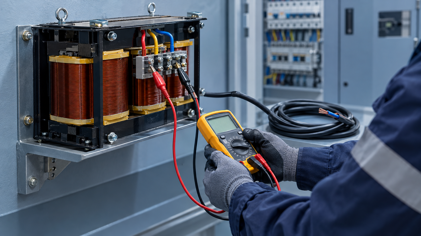
- Energise with the load disconnected, measure the output, then connect. If a boost reads below line voltage, the series leads are reversed: de-energise and swap them at the line side.
الأسئلة الشائعة
Is a buck-boost transformer the same as an autotransformer?
In construction yes, in application no. It is a two-winding transformer connected as an autotransformer, but its secondary is deliberately small and used in series, so it corrects a percentage of line voltage instead of the whole load.
Can a buck-boost transformer create a neutral?
No. The windings are shared, so the output is not a separately derived system. Any neutral the load needs must come from the source, and the series winding must never be placed in the neutral.
How much voltage can it correct?
In practice 5–20%, with about 25% as a ceiling. Standard 12, 16, 24, 32 and 48 V secondaries cover most 120–480 V applications; above that range a two-winding transformer is more economical.
Can I reverse the input and output to switch from boost to buck?
Do not. The primary stays on the supply and the mode changes only by swapping which secondary lead reaches the line. Reversing it changes the effective ratio and the kVA the unit can carry.
Does it work on 50 Hz?
Only after derating: limit applied voltage to roughly 83% of the 60 Hz rating. Units of about 0.75 kVA and below are sometimes wound for dual frequency, so check the nameplate rather than assuming.
The Short Version
A buck-boost transformer is the cheapest way to move a voltage by 5–20% when the mismatch is known and the supply steady. Size it on the differential — load current times correction voltage — not on load kVA, and it will be far smaller than you expect. Check the two safety limits first: no isolation, no new neutral. If either is required, this is the wrong product.
If the ratio is larger than a buck-boost can deliver, the next step is a two-winding unit; this guide to choosing the right step-up transformer covers the sizing logic from the other direction. Send us the measured line voltage, the load nameplate and the load current, and we will reply with a connection diagram and a rating rather than a catalogue page.