Transformer Live Wire and Neutral Wire: How to Connect Them Correctly
Veröffentlicht: Autor: Lisa
Connecting the Live Wire and Neutral Wire: The Short Answer
Connecting a transformer looks simple — two wires in, two wires out — yet reversed input wiring is one of the most common causes of shock hazards and nuisance tripping on low-voltage installations. The rule behind correct transformer wiring is straightforward: the live wire goes to the terminal marked L (or H1 on terminal-block models), the neutral wire goes to the terminal marked N, and the same identification discipline applies on the secondary side before anything is energized. Get it right and the transformer simply works; get it backwards and the equipment may still run — which is exactly what makes the fault so dangerous. This guide explains how to identify live and neutral conductors, connect them correctly on single-phase Aufwärts- und Abwärtstransformatoren, and what actually happens when the two are swapped.
What the Live Wire and Neutral Wire Actually Do
On any AC supply, the live wire (also called line or hot) carries the potential that pushes current through the circuit, while the neutral wire provides the return path and sits near earth potential. A transformer does not care which way electrons flow — it is an alternating-current device — but it does care which conductor carries ungrounded potential, because every downstream safety measure assumes the neutral is the grounded reference.
That is why the input terminals of a quality low-voltage transformer are marked L and N rather than + and −. The labels ensure that the protective device in front of the transformer, the fusing inside it, and the reference point of the output all land where the design intends. When the live wire lands on the neutral terminal, the transformer still produces its rated secondary voltage — but the internal reference is inverted, and several protection mechanisms stop working as intended.
Keep the two jobs separate in your head: the live conductor is the one you switch and fuse; the neutral conductor is the one you never open while the circuit is live. Terminal markings, wire colors, and testing all exist to keep those jobs from being confused.
How to Identify Live and Neutral Before Wiring
Wire identification should always happen with the supply isolated. There are three reliable layers of evidence; confirm at least two before terminating.
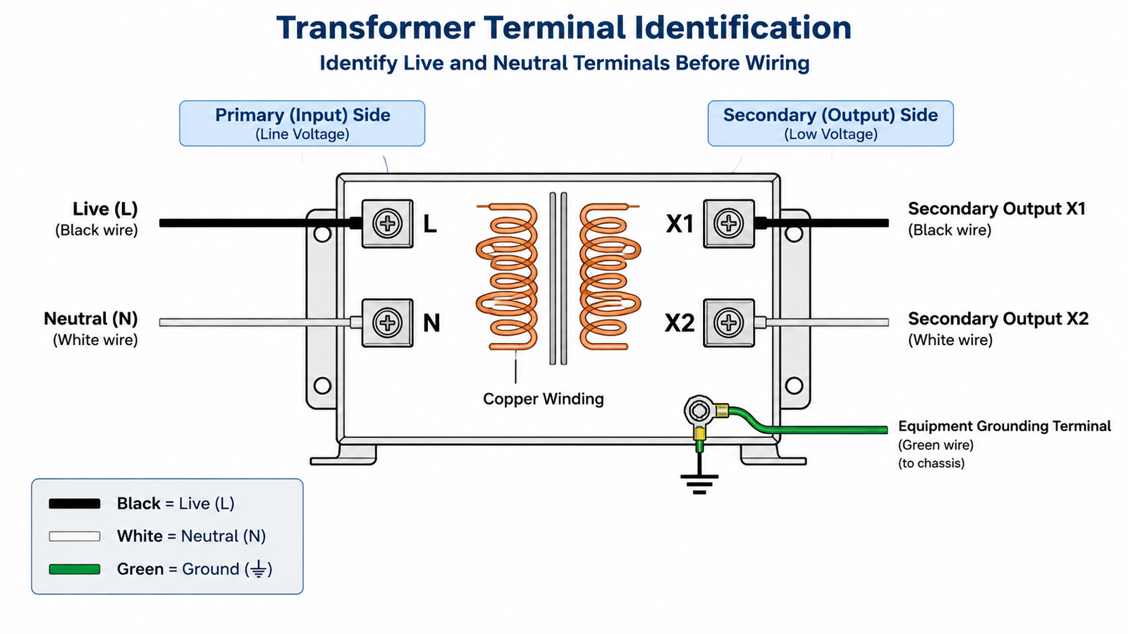
1. Read the Terminal Markings
Start at the transformer itself. Input terminals on single-phase units are typically stamped L und N; industrial terminal-block styles use H1/H2 for the high-voltage winding and X1/X2 for the low-voltage winding. The markings identify winding voltage class, not direction of power flow — a step-up unit still labels its 110 V winding as the low-voltage side even when it is acting as the input. Check the nameplate wiring diagram to confirm which winding matches your supply voltage before touching a screwdriver.
2. Follow the Conductor Colors — With Caution
Color conventions give the second layer of evidence, but they are regional, not universal:
Region
Live (Line)
Neutral
Protective Earth
IEC / EU / Asia (single phase)
Brown (or red)
Blue (or black)
Green-yellow
North America
Black (or red)
White
Green / bare
China (GB standard)
Brown, or yellow-green reserved for PE
Blue
Green-yellow
Treat color as a strong hint rather than proof. Imported equipment, older installations, and reused cables regularly break convention, which is why a functional test is the final confirmation.
3. Verify With a Tester or Multimeter
With the supply re-energized for testing only (and the load still disconnected), a contactless voltage tester or a multimeter between each conductor and a known earth point settles the question: the conductor reading full line voltage to earth is the live wire, the one near zero is the neutral. Re-isolate before making any termination.
Step-by-Step: Wiring the Live and Neutral Correctly
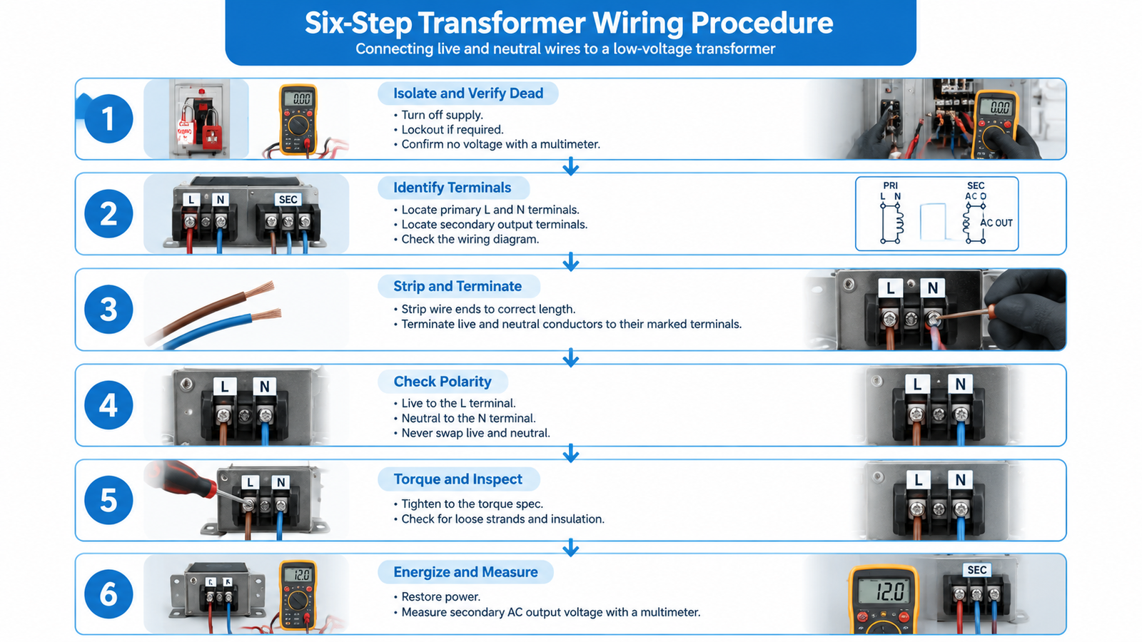
The following procedure suits typical 100 VA to 10 kVA single-phase transformers used for voltage conversion in workshops, export equipment, and machine control panels.
Isolate and verify dead. Switch off the supply, lock off if required, and confirm zero voltage at the point of connection with a multimeter.
Identify terminals and winding. Match the primary winding rating on the nameplate to your supply voltage, and locate the L and N input terminals plus the secondary output terminals.
Strip and terminate. Strip just enough conductor to fill the terminal fully, then land the live wire on L and the neutral on N. Loose strands and over-stripping are the two most common physical defects.
Check polarity and torque. Re-read the terminals: live to L, neutral to N, never swapped. Tighten to the specified torque — roughly 1–2 N·m on small screw terminals — and confirm insulation covers all bare conductor.
Erdung des Gehäuses. Connect protective earth to the ground lug on the frame. This is a separate conductor from the neutral and must never be combined with it on the load side.
Energize and measure. Restore power and measure the secondary output with a multimeter. It should read within a few percent of the nameplate voltage; a reading near half suggests a series/parallel winding strap is set for the wrong input voltage.
On the secondary side, the same identification logic applies: the winding terminal intended as the grounded conductor should be bonded to earth at the transformer where the installation design requires it, so the output behaves predictably for the equipment it feeds. For a three-phase unit, the L/N logic expands into L1/L2/L3 phase identification — see our three-phase transformer connection instructions for the full sequence.
What Happens If You Reverse the Live and Neutral
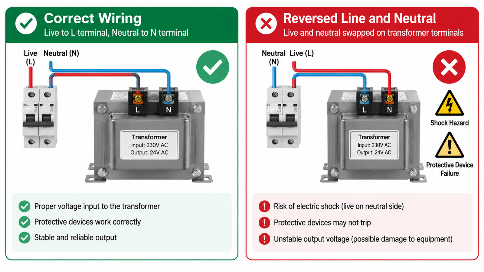
Here is the uncomfortable part: a transformer with swapped input wires will usually deliver its correct output voltage, and the connected equipment will often run normally. Nothing smokes, nothing trips — the fault stays hidden until one of three things happens.
Shock hazard on exposed parts. With the input reversed, the conductor that should be near earth potential now carries line voltage through parts of the circuit designed assuming a grounded neutral. Filter capacitors, switches, and chassis-referenced components can sit at line potential even when the equipment is switched off.
Protective devices stop protecting. A single-pole switch or fuse placed in the assumed-live conductor now interrupts the neutral instead. The circuit can be switched off and still be live at the terminals — the classic reason a “dead” machine shocks a technician.
Unstable or unsafe output reference. The secondary voltage may measure correctly between X1 and X2, but its relationship to earth is no longer what the downstream design assumes, which matters for control circuits, measurement, and any load with a grounded reference.
Because the transformer itself survives reversed wiring, the failure shows up on the human side — which is exactly why polarity checking before energizing is non-negotiable in any professional transformer wiring job.
Common Wiring Mistakes to Avoid
Most field problems trace back to a handful of repeat offenders:
Irrtum
Typical Symptom
Prevention
Live and neutral swapped on the primary
No visible fault until shock or nuisance trip
Verify L/N with a meter before energizing
Wrong winding strap for the supply voltage
Output at half voltage, or breaker trips instantly
Match nameplate diagram to actual supply
Undersized conductors or loose terminals
Hot terminals, voltage drop under load
Size for primary current; torque to spec
Neutral used as earth, or earth omitted
Unstable readings, RCD tripping, shock risk
Separate PE conductor to the frame lug
Load connected before output voltage check
Equipment damaged on first power-up
Measure secondary voltage before connecting load
For sizing context before you wire anything, it is worth revisiting why transformers are rated in kVA — most overloaded-transformer complaints begin with a load calculated on watts rather than volt-amperes.
Choosing a Transformer With Clear, Safe Terminals
Wire identification is far easier on units designed for international use. The JOHSUN DT/ST series step-up and step-down transformers (100 VA–10 kVA), for example, provide clearly marked input selection and standard outlet outputs, so wiring reduces to landing live and neutral on a labeled block and selecting the correct voltage position — the exact unit class this guide uses as its reference. For smaller control circuits, the ST series (100 VA–1500 VA) follows the same terminal layout in a compact wall-mountable housing.
FAQ
Does it matter which way you wire a transformer primary?
Electrically the transformer will still convert voltage, but yes — it matters. Reversed live and neutral invert the internal reference, disable single-pole switching and fusing on the true live conductor, and create a shock hazard. Always land live on L and neutral on N.
What happens if you connect live to neutral on a transformer?
The output voltage usually remains correct, so the fault stays hidden. The risks appear later: exposed parts can sit at line potential, protective devices interrupt the wrong conductor, and the output loses its intended earth reference.
How do I identify live and neutral wires if the colors are non-standard?
Isolate the circuit, then energize for testing only and measure each conductor to a known earth point with a multimeter. Full line voltage to earth identifies the live wire; near zero identifies the neutral. Re-isolate before terminating.
Should the transformer secondary be grounded?
In most industrial and export applications, one secondary terminal (or the center tap, where fitted) is bonded to earth at the transformer so the output has a defined reference. Follow the wiring diagram supplied with the unit and local electrical code.
Why does my transformer trip the breaker immediately after wiring?
An instant trip usually means the primary winding straps are configured for the wrong input voltage, a shorted or pinched conductor at the terminals, or a shorted load on the secondary. Re-check the nameplate diagram and terminal torque before re-energizing.
Can one transformer accept both 110V and 220V input?
Dual-voltage models can, via series or parallel winding straps selected per the nameplate diagram. Wiring the straps for 110 V and applying 220 V will saturate the core and trip the breaker instantly, so this check belongs before every installation.
Fazit
Correct transformer wiring comes down to disciplined wire identification: confirm the terminal markings, treat conductor colors as a hint rather than proof, verify with a meter, and land the live wire on L and the neutral on N before anything is energized. The transformer rarely complains about reversed wiring — the people around it do — so the polarity check you skip is the one that gets tested by hand later. For more guides like this, browse the transformers knowledge base, or contact the JOHSUN team for help matching a unit to your supply and load.
Compare single-phase and three-phase transformers on windings, capacity, voltage stability, efficiency, and cost — then pick the right one for your load and supply.
A three-phase transformer can supply single-phase loads — but only with the right winding tap and the right derating. Here's the wiring, the math and the limits.