A Steuertransformator is the small step-down transformer inside an electrical panel that turns a 220 V, 380 V or 480 V supply into the 120 V or 24 V that relays, contactor coils, timers, pilot lights and PLC inputs run on. It is not there to move bulk power, but to hold a stable voltage while the machine’s logic switches on and off, and to keep that logic galvanically separated from the power circuit. This guide covers how the turns ratio produces the control voltage, why inrush current rather than steady-state load decides the VA rating, and how to size, wire and protect one correctly.
Was ist ein Steuertransformator?
A control transformer is a dry-type step-down transformer built to supply a dedicated, stable low voltage to the control and auxiliary circuits of a machine or panel. Its defining characteristic is intent rather than size: a distribution transformer transfers power efficiently, while a control transformer holds its secondary voltage steady while the connected load changes suddenly.
That matters because control circuits are not steady loads. A contactor coil drawing 10 VA while sealed may demand 60 VA or more for the few milliseconds it takes to pull in, and the transformer must ride through that surge without the voltage sagging far enough to make the contactor chatter or drop out.
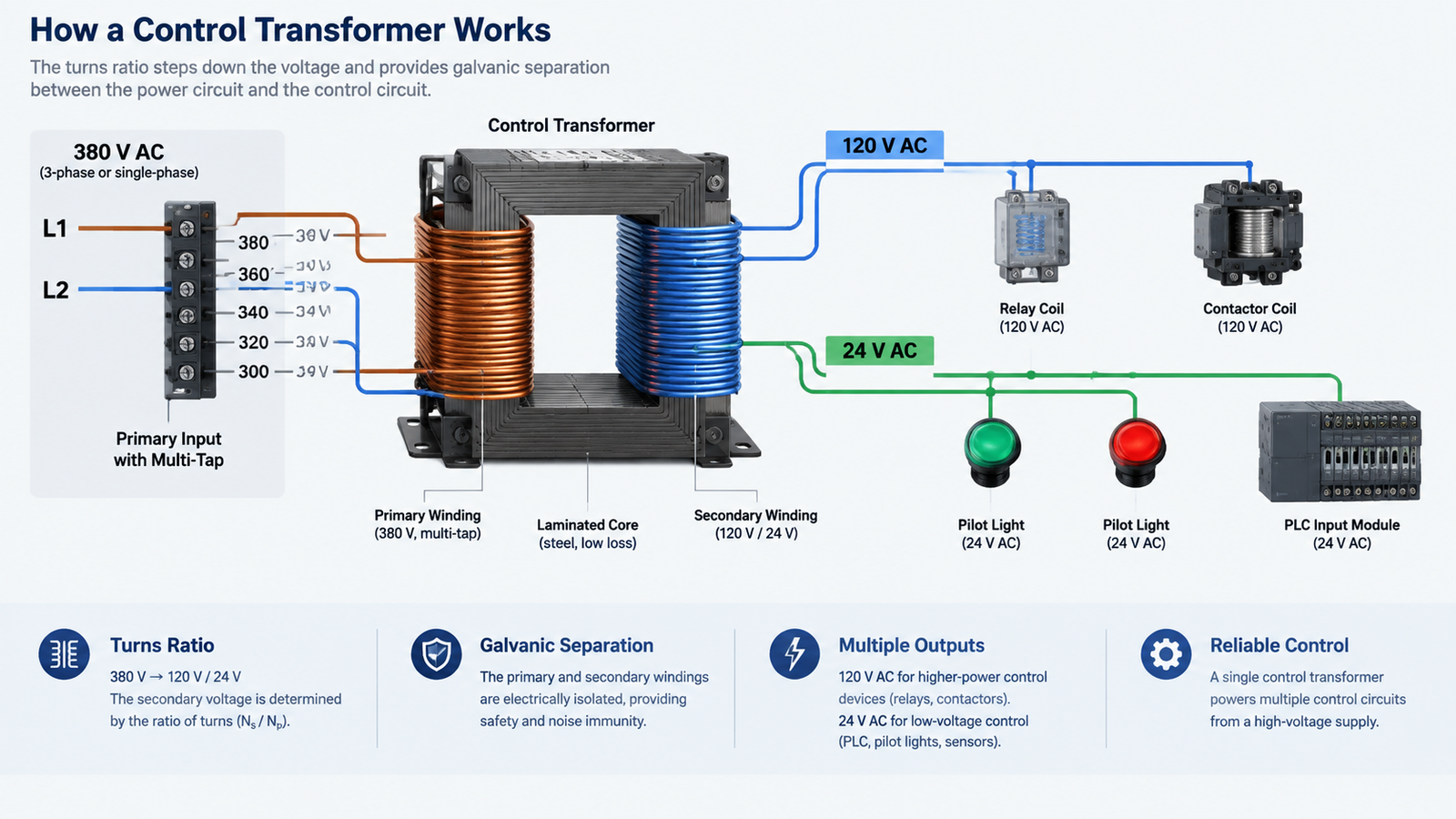
Published specifications follow a recognisable pattern: 40 VA to 2.5 kVA, a 220 V or 380 V primary with ±5% taps, and often three separate secondary windings — 110 V (or 127 V) for control, 24 V (or 36 V) for machine illumination, and 6 V (or 12 V) for indication lamps. That multi-winding arrangement clearly separates a control transformer from a general-purpose unit of the same VA rating.
How a Control Transformer Works
The voltage transformation itself is ordinary. What is engineered is the behaviour under load.
The Turns Ratio Sets the Control Voltage
Alternating current in the primary creates magnetic flux in the laminated core, and that flux induces a voltage in the secondary. The turns ratio fixes the output: a 380 V primary wound at 19:6 delivers about 120 V. Because the windings are linked only by the magnetic field, a fault on the power side cannot propagate onto the start and stop buttons an operator touches. A laminated silicon-steel iron core structure keeps eddy-current and hysteresis losses low — which matters inside a sealed panel — and sets how much flux the transformer carries before it saturates during a switching surge.
Load Regulation Is the Design Priority
Voltage regulation is the percentage change in secondary voltage between no load and full load. A control transformer is wound with low internal impedance and generously sized conductors so that figure stays small — typically 3% to 5%, against 5% to 8% for a general-purpose unit of the same VA — keeping the output inside the working range of the coil at peak demand. Efficiency is secondary; a stable 120 V under a changing load is the point.
Inrush Current Drives the VA Rating
This is the part most buyers get wrong. The VA figure is not the sum of the steady-state loads. Electromechanical devices — contactors, relays, solenoid valves, brakes — draw a large magnetising surge for the first few cycles after energising. If every device can start on one command, the transformer must supply that combined surge without the voltage collapsing far enough to stop the coils sealing.
Control transformers are therefore specified with an inrush VA rating quoted at a defined voltage drop, typically 5% or 10%. The rating convention in volt-amperes already accounts for the phase relationship between voltage and current, but says nothing about the transient — which is why the inrush column decides whether the panel works.
Wo werden Steuertransformatoren eingesetzt?
The pattern repeats across industries: a machine has a high-voltage power section and a low-voltage thinking section, and the control transformer is the boundary. In machine control panels and automation cabinets, three jobs recur — step the voltage down, isolate the operator interface, and hold the output steady while coils switch.
Anmeldung
Typical control voltage
Why a dedicated transformer is used
Machine tool control panel
110 V or 120 V AC
Keeps operator controls off the 380 V or 480 V supply
Automation and PLC cabinet
24 V AC or DC
Matches the I/O module, sensor and valve range
HVAC air handling unit
24 V AC
Powers thermostats, damper actuators and valves
Motor control centre and starter
120 V AC
Coil supply independent of the motor bus voltage
Panel illumination and indication
24 V or 6 V
Separate winding keeps lamp load off the control circuit
Control Transformer vs General-Purpose Transformer
The two look alike on a shelf and are not interchangeable in service. For a heater bank or lamp circuit with no coils, a general-purpose transformer will do. For a set of contactors that switch together, the inrush specification is what you are buying.
Characteristic
Control transformer
General-purpose transformer
Design goal
Stable secondary voltage
Efficient power transfer
Voltage regulation
Typically 3% to 5%
Typically 5% to 8% or looser
Inrush capability
Specified at 5% or 10% voltage drop
Rarely specified; not a design target
Primary winding
Multi-tap for 208 V, 240 V, 380 V, 400 V, 480 V
Usually a single fixed primary voltage
Secondary
Often two or three separate windings
Normally one winding
Schutz
Designed for primary and secondary fusing
Protected upstream only
How to Size a Control Transformer
Sizing is a three-step calculation, and the answer almost always comes from step two rather than step one.
Step 1 — Add the Sealed VA of Every Device
List every control device the transformer will feed and add the sealed (holding) volt-amperes. This sets the thermal minimum: the continuous load the transformer must carry without exceeding its rated temperature rise.
Step 2 — Add the Inrush VA of Everything That Can Start Together
Identify which devices can energise simultaneously and add their inrush VA — not their sealed VA — for that worst-case moment. This is the number that actually selects the size.
Step 3 — Match Both Figures to a Standard Rating
Choose the smallest standard size whose published inrush VA, at the voltage drop your coils can tolerate, exceeds the step-two total while its continuous rating covers the step-one total.
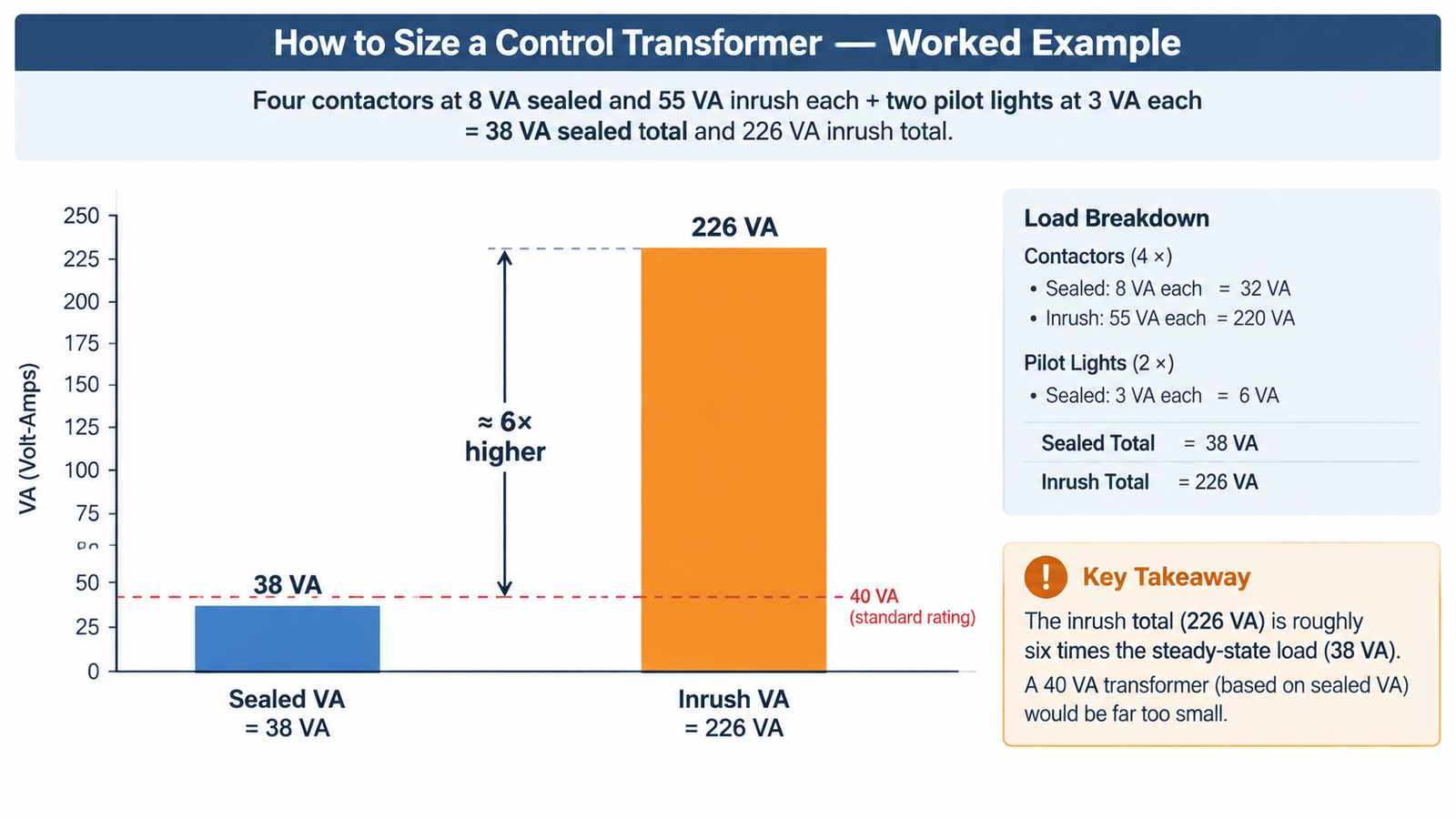
Suppose a panel carries four contactors at 8 VA sealed and 55 VA inrush each, plus two pilot lights at 3 VA each. The sealed total is (4 × 8) + (2 × 3) = 38 VA. The inrush total, with all four contactors commanded together, is (4 × 55) + (2 × 3) = 226 VA. The steady-state figure points at a 40 VA unit, but a transformer chosen on sealed VA alone will let the voltage sag at exactly the moment the contactors need to seal. A six-to-one ratio between inrush and sealed VA is normal in contactor-heavy panels, which is why control transformers are routinely specified one or two standard sizes above the arithmetic minimum. Read the inrush column for the size you are considering rather than extrapolating from the nameplate.
Voltage Taps, Fusing and Grounding
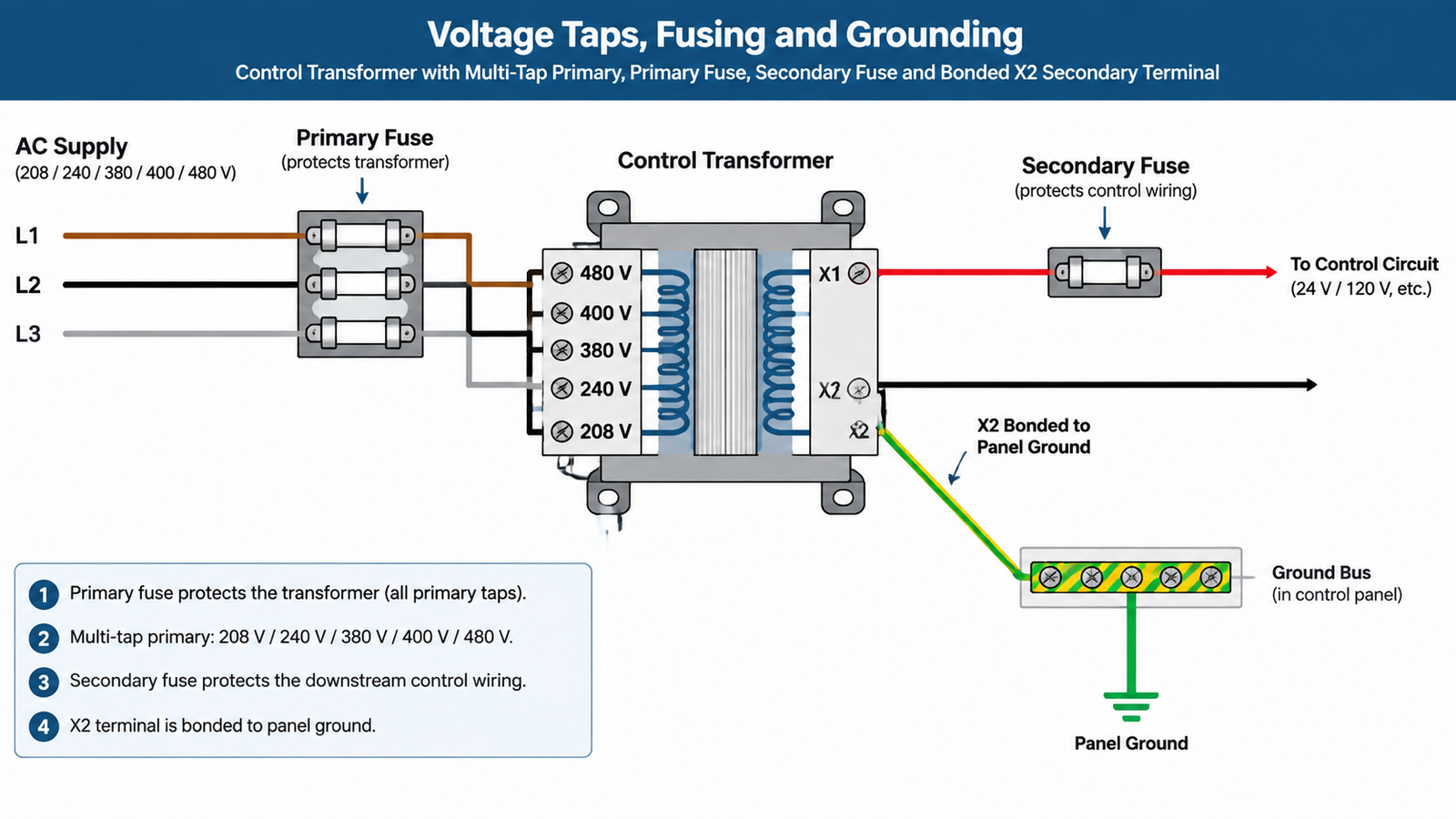
Choose the tap that matches the real supply. A multi-tap primary only helps if the tap reflects the measured site voltage. Landing a 380 V supply on the 400 V tap leaves the secondary about 5% high, running every coil and lamp hotter. Measure first, then tap.
Fuse both sides. The primary fuse protects the transformer from an internal fault or upstream overcurrent; the secondary fuse protects the control wiring and downstream devices from a short or sustained overload. Both are normally required by the wiring code applicable to motor control circuits.
Bond one secondary terminal. Grounding one end of the secondary — usually X2 — gives a ground fault a return path so the secondary fuse opens instead of the fault persisting unnoticed. Leave the secondary floating only when the circuit is deliberately isolated. When the panel is fed from a three-phase source, confirm the supply configuration before landing conductors; the connection arrangements differ between star and delta supplies and between earthed and unearthed systems.
Feeding the Panel from the Wrong Site Voltage
One recurring problem has nothing to do with the transformer’s own rating. An imported machine arrives wired for 220 V and is installed on a 110 V site, or the reverse. The control circuit then sits on the wrong voltage no matter which primary tap is selected, and the fix is a step-up or step-down transformer ahead of the panel rather than an oversized control transformer. A unit such as the DT-3000VA step-up and step-down transformer handles that supply-side conversion, so the control transformer downstream sees the voltage it was designed for; the comparison of autotransformers and control transformers covers where each family belongs. For a purpose-built unit with the multi-winding secondary described above, the JBK3 series control transformer covers 40 VA to 2500 VA with a 220 V or 380 V primary and separate control, illumination and indication windings.
Häufig zu vermeidende Fehler
Irrtum
Was passiert?
Correct approach
Sizing on sealed VA only
Voltage sags during inrush; contactors chatter or fail to seal
Size on the inrush total at the permitted voltage drop
Ignoring simultaneous starting
Real surge is larger than the calculated one
Assume every device on one command can start together
Wrong primary tap
Secondary runs high or low, stressing coils and lamps
Measure the site voltage and tap to it
Secondary left floating by accident
Ground faults go undetected
Bond X2 deliberately, or isolate deliberately
No secondary fuse
Control wiring unprotected; transformer takes the fault
Protect both sides
A control transformer that runs persistently hot is usually undersized for the duty, not faulty. Persistent overheating degrades winding insulation well before the transformer fails outright, so treat a hot case as a sizing signal rather than a ventilation problem.
Fazit
A control transformer exists to give a machine’s control logic its own clean, isolated, stable voltage — and the number that decides whether it does that job is the inrush VA figure, not the sealed load. Add the holding VA to set the thermal floor, the inrush VA of everything that can start together to set the real requirement, tap the primary to the measured supply voltage, and fuse both sides.
If you are specifying a control transformer for a machine build or retrofit, send us the supply voltage, the control voltage you need, and the list of coils on the circuit — we will match the winding configuration and VA rating to the duty.
FAQ
What is the difference between a control transformer and an isolation transformer?
Both provide galvanic separation but are optimised differently. An isolation transformer is designed primarily for separation and noise rejection, usually at a 1:1 ratio. A control transformer combines separation with a deliberate step-down ratio and is specified for voltage regulation and inrush capability, so coils can be switched repeatedly without the output sagging.
What output voltage does a control transformer provide?
Common control outputs are 120 V AC and 24 V AC. Industrial designs frequently add a second winding at 24 V or 36 V for machine illumination and a third at 6 V or 12 V for indication lamps, so lighting loads do not disturb the control winding.
Can a general-purpose transformer be used as a control transformer?
It can be used where the load is resistive and steady, such as a heater or lamp bank. It is a poor choice for contactor and relay loads because its inrush capability is not specified and its regulation is looser, so the secondary voltage may drop enough during switching to prevent coils sealing reliably.
230-V-auf-110-V-Transformator für die Niederlande: NEN 1010, 30-mA-Fehlerstromschutzvorschriften, „Aardlekschakelaar“ versus „Aardlekautomaat“ und Sekundärerdung.