How to Measure DC Resistance of Transformer Windings or Motor Coils
Veröffentlicht: Autor: Lisa
What DC Resistance Measurement Tells You
Measuring the DC resistance of a transformer winding or a motor coil is the fastest way to find a defect no visual inspection will reveal. The test is almost trivially simple: push a known direct current through the winding, measure the voltage drop, and divide. What separates a defensible measurement from a misleading number is everything around those three actions — how the leads are attached, how long you wait, what temperature the winding is at, and what you compare the result against.
This guide covers the full procedure for both transformer windings and motor coils, including the parts most write-ups skip: when a four-wire meter is genuinely necessary, how to correct readings to a reference temperature, and how to judge whether a result means pass or investigate. It is aimed at commissioning checks and routine transformer testing on dry-type and low-voltage units, not only utility-scale power transformers.
Why Winding Resistance Matters
Winding resistance measures the conductor path directly. Anything that adds resistance, removes a parallel path, or shorts turns together changes that number predictably. Three findings account for most of the value of a winding test.
Turn-to-turn and layer shorts
A short between adjacent turns creates a closed loop that circulates current, overheats locally, and removes conductor length from the circuit. The affected phase reads slightly lower — often by a fraction of a percent, which is why phase and baseline comparison both matter. In a small transformer, one shorted turn can raise losses enough to destroy insulation within hours.
Tap changer and connection defects
Tap contacts, terminal blocks, and bolted joints all sit in series with the winding. A pitted contact or oxidised terminal shows up as a higher reading on one tap position or one phase. This is the most common real-world finding and the easiest to fix — which is what makes a winding test worth running rather than merely diagnostic. A resistance that jumps at one tap and recovers at the next points almost directly at the tap changer.
Strand breakage and baseline tracking
Large windings use multiple parallel strands; if one breaks, the winding still conducts through less copper and resistance rises — invisible to a ratio or insulation test. And even when nothing is wrong, the first reading has value: corrected to a common temperature, it becomes the baseline every later test is compared against. For how the winding and core are arranged, see this explanation of Transformatorenkonstruktion und Eisenkernstruktur.
Equipment and Setup
DC resistance meter or winding ohmmeter. Dedicated instruments stabilise the reading automatically and discharge the winding safely. A bench multimeter works on small units if it resolves to 1 mΩ.
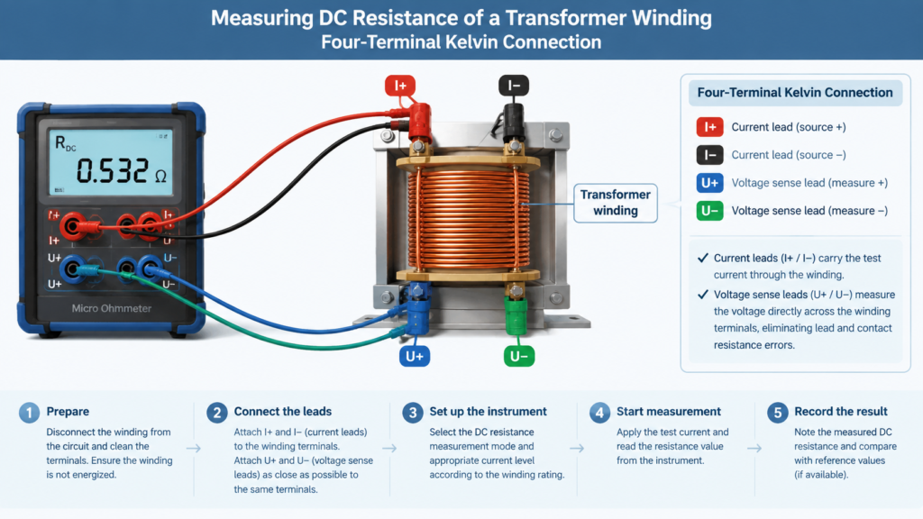
Test leads rated for the current. Kelvin (four-terminal) clips preferred.
A thermometer, insulated gloves, and a discharge rod. Winding temperature is required for correction, and the winding stores inductive energy that must be released before you touch a connection.
When four-wire measurement is actually necessary
Generic advice over-engineers this. A four-terminal (Kelvin) connection separates the current-carrying leads from the voltage-sensing leads, so lead resistance never enters the measurement. It is mandatory when winding resistance is in the same order of magnitude as lead resistance — on utility power transformers, where a phase may read a few milliohms.
Small dry-type units are different: a 1 kVA winding commonly reads from half an ohm to several ohms, while clean leads contribute only 0.05 to 0.1 Ω. Null the lead resistance with the meter’s relative function, keep clips tight, and verify the null before each phase.
Choosing the test current
Current must be high enough for a stable voltage drop and low enough that winding heating does not shift resistance mid-measurement.
Winding resistance
Typical test current
Practical note
Below 1 Ω
10 A or more
Four-wire mandatory; settling may take minutes
1 – 10 Ω
1 A to 5 A
Common range for small dry-type transformers
10 – 100 Ω
0.1 A to 1 A
Control and instrument transformer windings
Above 100 Ω
Below 0.1 A
Two-wire acceptable with lead nulling
Higher current gives a stronger signal but heats the winding faster. On small units, staying at 1 A to 5 A is the better trade. For how much current a winding is rated to carry in service, see why transformers are rated in kVA.
Step-by-Step Procedure
Isolate and lock out. Disconnect every source on every side and verify zero energy at the terminals.
Discharge and ground. Leave the winding grounded until the moment you connect the test leads.
Clean the terminals. Remove oxidation and paint — a dirty clip adds resistance to your measurement.
Record the conditions: winding temperature, ambient temperature, tap position, and terminal pairs.
Connect the leads. For four-wire, place the voltage sense leads inside the current leads.
Apply the current and watch the display. Do not record the first stable-looking number you see.
Wait for true settling. The reading is valid only once the inductive transient has decayed. Small windings settle in under a second; large ones can take minutes.
Record every phase and every tap position , with the tap noted beside each value.
Discharge before every reconnection. Never open a test lead while current is flowing.
Correct all readings to a reference temperature before comparing anything.
Measuring Motor Coils
The physics is identical, but access is the problem. On a three-phase motor, the internal connection determines what you can measure without opening the machine.
Star, star point inaccessible: line-to-line measurement puts two windings in series, so the reading is roughly double a single phase — expected. Compare the three line-to-line values against each other.
Delta: a line-to-line measurement sees one winding in parallel with two in series. Phase balance is the primary signal rather than absolute value.
Star point accessible or machine opened: measure each phase individually. This is the only way to isolate a single defective phase directly.
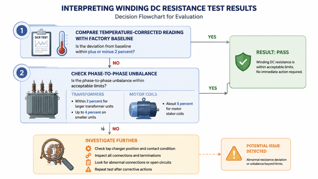
Motor coils use heavier conductor than a transformer of similar frame size, so readings are lower and four-wire measurement becomes more relevant, while high inductance means longer settling. Phase imbalance is judged more loosely — many programmes accept about 5%, though the manufacturer’s tolerance governs. This is also not a substitute for insulation resistance testing, which measures the path to ground.
Temperature Correction
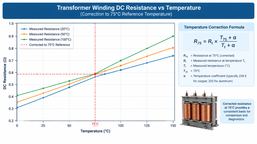
Copper resistance rises with temperature at roughly 0.39% per degree Celsius, so a reading taken on a warm winding can easily be 15% higher than the same winding measured cold. Comparing an uncorrected value against a factory figure measured at another temperature produces a false fault — or hides a real one. Use the standard copper relationship:
For aluminium windings, substitute 225 for 234.5. A winding measuring 2.40 Ω at 32 °C, corrected to a 75 °C reference:
R ref = 2.40 × (234.5 + 75) ÷ (234.5 + 32)
R ref = 2.40 × 309.5 ÷ 266.5 = 2.40 × 1.161
R ref = 2.79 Ω
The correction adds 16% — far larger than the tolerance you are testing against. Measure temperature as close to the winding as possible.
Interpreting the Results
Vergleich
Commonly applied limit
What a failure suggests
Deviation from factory or baseline
Within ±2% after correction
Deformation, strand breakage, joint degradation
Phase-to-phase unbalance
Within 2% on larger units; up to 4% on smaller
A single-phase fault — tap contact, terminal, or shorted turn
Consistency across tap positions
Monotonic, predictable change
A discontinuity points at the tap changer
Stability over time
Stable within seconds of settling
Creeping values indicate a test-circuit problem, not the winding
Compare like with like: temperature-corrected against temperature-corrected, same tap position, same terminal pairs. Where the manufacturer supplies factory data, that data governs over generic limits.
Common Mistakes
Reading during the inductive transient. The largest single source of error. Wait for the display to stop moving.
Ignoring temperature. Comparing a hot reading to a cold baseline creates phantom faults.
Dirty or loose clips. Contact resistance adds directly to the measurement.
Testing only one phase. Unbalance is the most sensitive indicator available, and it needs a comparison.
Skipping tap positions. A tap changer fault is invisible at a single position. On multi-winding units, the winding arrangement determines which terminal pairs belong to which circuit.
Reconnecting before discharge completes. The winding stores magnetic energy and will return it.
Putting the Test Into Practice
DC resistance measurement earns its place because it is the only routine test that looks directly at the conductor path. Ratio tests confirm turns; insulation tests confirm isolation. Neither will tell you that a tap contact has pitted or that a parallel strand has broken. A temperature-corrected reading, compared phase to phase and against a recorded baseline, catches those problems while the equipment is still on the bench — and a dry-type or Steuertransformator with a clean history is far easier to diagnose later, because you know what normal looks like for that winding.
If you are specifying new equipment and want factory resistance data supplied with the test certificate, browse the step-up and step-down transformer range, or look at a specific example such as the STU series 100 VA to 2 kVA to see the ratings and connection details you would be working with.
FAQ
What is a normal DC resistance for a transformer winding?
There is no universal value — it depends on rating, voltage class, and conductor size. A small 1 kVA dry-type unit may read from half an ohm to several ohms, while a utility power transformer phase can read a few milliohms. The meaningful reference is the manufacturer’s factory value or your own baseline for that winding.
Can I measure winding resistance with an ordinary multimeter?
Yes, for higher-resistance windings such as small control transformers — provided the meter resolves to 1 mΩ, you null lead resistance using the relative function, and the reading is stable. Below roughly 1 Ω, use a four-wire winding ohmmeter.
Why does my reading keep climbing instead of settling?
Either the winding is still heating from the test current, or there is a poor connection in the test circuit. Reduce the current and retry, and check that the clips are clean and tight.
How long should I wait before recording the value?
Until the display stops changing. On small transformer windings that is often under a second; on large power transformer windings it can take several minutes. A value captured before the transient decays is not the DC resistance.
What phase unbalance is acceptable on a motor coil?
Many maintenance programmes accept a phase-to-phase spread of about 5% on motor stator windings after temperature correction — looser than the 2% to 4% typically applied to transformer windings. The motor manufacturer’s tolerance always takes precedence.
230-V-auf-110-V-Transformator für die Niederlande: NEN 1010, 30-mA-Fehlerstromschutzvorschriften, „Aardlekschakelaar“ versus „Aardlekautomaat“ und Sekundärerdung.