If a three-phase transformer has a shorted turn or a faulty core, it will still pass a basic resistance check — and then fail in service. The magnetic balance test is the quick, low-voltage check that catches these faults before energisation: you energise one phase of a winding with a single-phase AC supply, measure the voltages induced in the other two phases, and compare the pattern. The whole test takes under 30 minutes and needs nothing more than a variac, a voltmeter, an ammeter and a test sheet. This guide covers the setup, the procedure, the test-voltage choice most guides get wrong, both measurement channels, and the false positives that fail healthy units. It is one of the routine checks in our transformer testing and selection guides.
What the Magnetic Balance Test Actually Measures
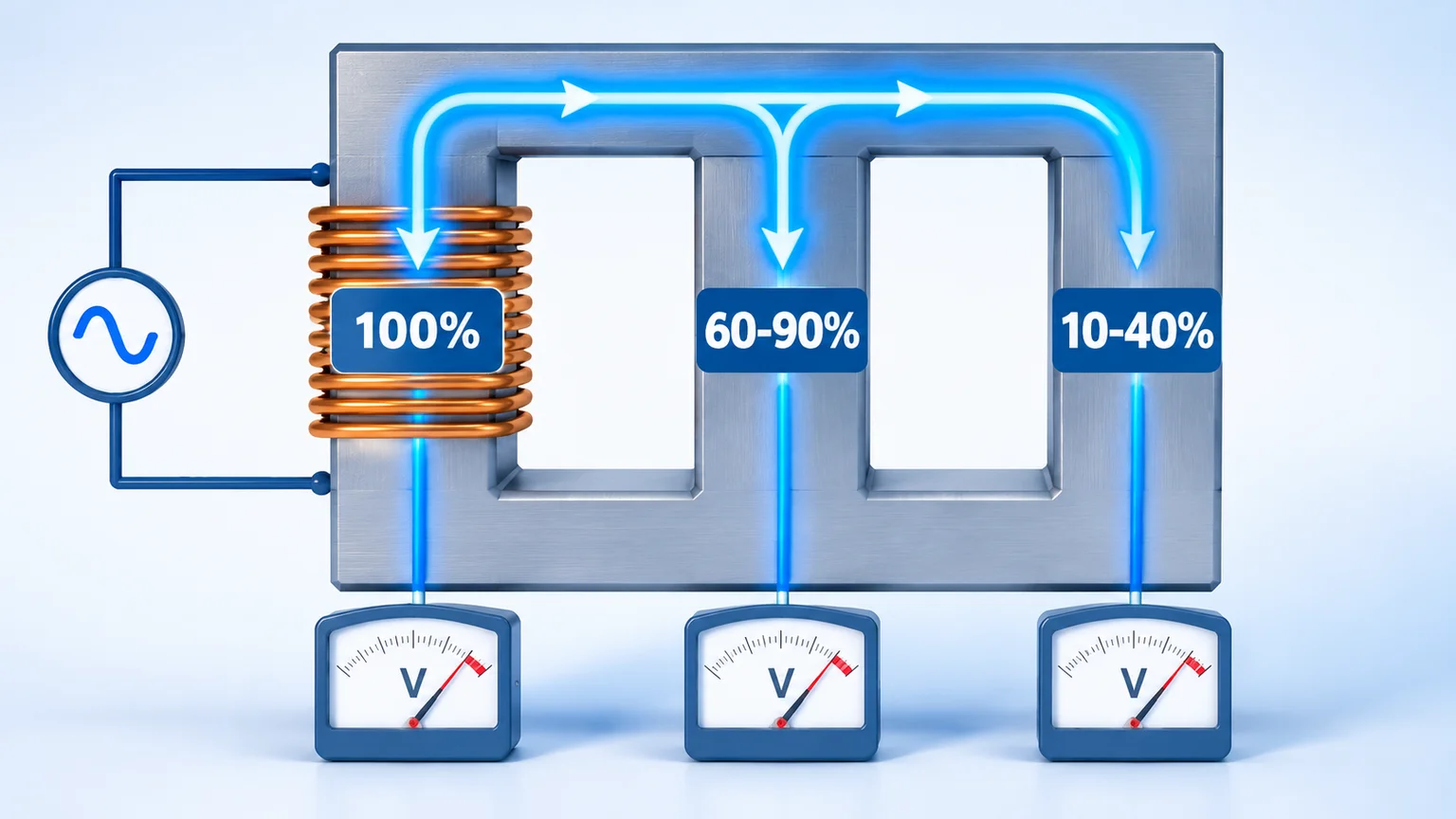
On a three-limb core, each phase winding sits on its own limb, and all three share the same yokes. When you excite one limb, its flux must return through the other two, so flux continuity at the top yoke fixes the relationship: the flux in the excited limb equals the sum of the fluxes in the other two. Since induced voltage is proportional to flux (at equal turns per phase), the induced voltages must add back up to the applied voltage.
The split between the two return limbs is not 50/50, though. The adjacent limb offers a shorter, lower-reluctance iron path, so it takes the majority of the flux — typically 60–90% — while the far limb takes the rest. What matters is that the pattern is stable and repeatable, because the split is a signature of the core’s geometry: window proportions, joint stacking, and whether the core has three limbs or five — all covered in our guide to Transformatorenkonstruktion und Eisenkernstruktur.
Setup: Six Checks Before You Energise
- Isolate and disconnect. The transformer must be fully disconnected from the network, including the neutral earth on star windings — a grounded neutral shorts the measurement path.
- Fix the tap position. Put the tap changer on its nominal position and write it down; every step off nominal shifts the induced voltages.
- Confirm the winding arrangement. You need access to both ends of each phase. Star with a brought-out neutral is straightforward; delta windings are tested phase-to-phase with a different pattern.
- Pick the excitation winding. On a two-winding unit, exciting the LV winding at reduced voltage and measuring on the HV side gives the best signal levels.
- Demagnetise if needed. If the unit has just been through a DC test, residual magnetism will bias every reading.
- Check the meter. Use a true-RMS voltmeter with high input impedance — near saturation the induced waveform is distorted, and an average-responding meter reads it differently.
How to Run the Test, Step by Step

- Connect the variac output and an ammeter in series to the first phase winding (A–N on a star winding), with the voltmeter connected across each of the other two phases.
- Ramp the voltage up slowly to your target value while watching the current — a healthy limb takes a small, stable magnetising current.
- Record four values: the applied voltage, the magnetising current, and the two induced voltages.
- Return the variac to zero, move the supply to the second phase, and repeat. Then do the third, using the same applied voltage throughout.
- If time allows, repeat the full sequence on the other winding.
Always ramp down to zero before moving leads; disconnecting under voltage leaves residual flux that skews the next reading.
Choosing the Test Voltage: Where Most Guides Go Wrong
Core flux is proportional to applied voltage divided by frequency and turns, so the same 230 V source produces completely different flux levels depending on which winding you excite. On an 11 kV HV winding, 230 V is roughly 2% of rated flux — very linear, but the induced voltages are small and meter resolution suffers. On a 400 V LV winding, 230 V is already about 57% of rated flux, close enough to the knee of the magnetising curve to distort the split.
| Excited winding (11 kV / 400 V unit) |
Applied voltage |
Approx. core flux |
Comment |
| 11 kV HV winding |
230–400 V |
2–4% |
Very linear, but signals are small |
| 400 V LV winding |
40–80 V |
10–20% |
Best balance of signal and linearity |
| 400 V LV winding |
230 V |
≈57% |
Risky: near the knee, the split stops being linear |
The practical rule: keep excitation at roughly 5–20% of the winding’s rated voltage. If you over-excite, the flux split goes nonlinear and the “sum of induced equals applied” relationship degrades — you will fail a perfectly good transformer. This is the same saturation physics behind inrush current, explained in our article on Sättigung des Transformatorenkerns.
A variac is the safest way to get there — you bring the voltage up from zero while watching the current. Our TDGC2J variable transformers (0.5–5 kVA) are built for exactly this kind of bench work.
Reading the Results: Three Criteria That Actually Hold
You will find the same expected-pattern table on every page about this test. For a healthy three-limb core with equal phase windings:
| Phase energised |
Adjacent phase induced |
Far phase induced |
| Left (A) |
60–90% of applied |
10–40% of applied |
| Middle (B) |
≈50% of applied |
≈50% of applied |
| Right (C) |
10–40% of applied |
60–90% of applied |
Here is the part most guides omit: that table is a geometry signature, not a pass/fail limit. No IEC or IEEE standard defines numerical acceptance values for this test, and a 60/40 split can be perfectly healthy on one core and suspicious on another. What holds on any healthy three-limb unit are three self-consistency criteria:
- The sum check: the two induced voltages add up to the applied voltage, within a few percent.
- Outer-limb symmetry: exciting A produces a mirror image of exciting C, within roughly 5%.
- Middle-limb symmetry: exciting B splits almost equally between A and C.
A baseline from a known-good sister unit or the factory’s original record is worth more than any published table. A healthy record on a distribution transformer looked like this:
| Excited |
Applied |
Reading 1 |
Reading 2 |
Sum |
Aktuell |
| A–N |
230 V |
B–N: 177 V (77%) |
C–N: 56 V (24%) |
233 V (101%) |
135 mA |
| B–N |
230 V |
A–N: 115 V (50%) |
C–N: 114 V (50%) |
229 V (100%) |
99 mA |
| C–N |
230 V |
A–N: 56 V (24%) |
B–N: 175 V (76%) |
231 V (100%) |
135 mA |
Notice the current column: the outer limbs draw almost equal current, both higher than the middle limb — normal on three-limb cores, and it brings us to the channel most guides ignore.
When the Pattern Breaks: Read Both Channels
A shorted turn is a closed loop with almost no impedance. Its circulating current opposes the core flux, so the affected limb carries less flux and demands more current from the supply. That gives two independent channels, and they disagree in a characteristic way: the voltage channel shows where flux collapses, the current channel shows where excitation demand rises.
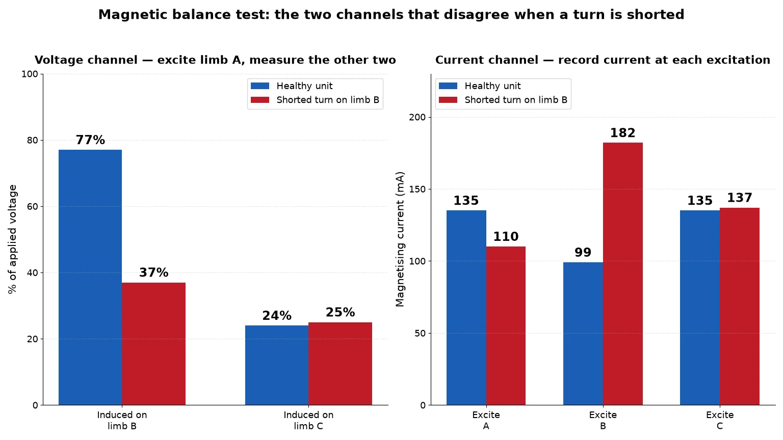
In the chart, exciting limb A on the healthy unit induces 77% on limb B; with a shorted turn on limb B, that reading collapses to 37% while the far limb stays near 25%. The current channel agrees: exciting limb B now draws 182 mA instead of 99 mA.
| Voltage pattern |
Current pattern |
Wahrscheinlichste Ursache |
| Normal split, sum ≈ applied |
Normal, outer limbs ≈ each other |
Healthy unit |
| One induced reading collapses whenever that limb participates |
Current jumps 30–100% when exciting that limb |
Shorted turns on that limb |
| Normal |
All currents high and asymmetric |
Core problem: shorted laminations or failed core bolt insulation |
| Pattern shifted, readings not repeatable |
One limb’s current unusually low |
Residual magnetism biasing the core |
| Readings drift between repetitions |
Unstable |
Tap position changed, poor connection, or meter issue |
Core-related current symptoms tie into no-load behaviour, covered in our article on transformer no-load losses — high magnetising current here usually means elevated no-load loss on the OC test too.
Four False Positives That Fail Healthy Transformers
- Residual magnetism. A freshly DC-tested unit — or one switched off under load — carries remanent flux that biases the pattern, typically pulling one limb down by 10–20%. Demagnetise with AC ramped slowly to zero, or wait 24 hours and retest.
- Wrong tap position. Two taps off nominal can shift induced voltages enough to look like a fault. Always confirm the tap changer is on the recorded position.
- Over-excitation. Exciting near the knee of the magnetising curve breaks the sum rule and makes a good transformer look unbalanced. Drop the test voltage and retest before condemning anything.
- Meter and lead errors. An average-responding meter on a distorted waveform, or a high-resistance jumper in the measuring path, mimics a real fault. Swap meters and re-seat connections before writing a failure report.
When the Test Does Not Apply
The magnetic balance test is a three-phase, three-limb test. It is meaningless — or actively misleading — on:
- Single-phase transformers. There is no multi-limb magnetic circuit to balance. Most units in the 100 VA to 10 kVA class — including our DT, ST, STU and TDGC2J ranges — are single-phase; screen them with the turns ratio test, no-load current and DC resistance instead.
- Five-limb cores. The two extra outer limbs give the flux additional return paths, so the 60–90/10–40 table does not describe them.
- Toroidal and wound cores. No discrete limbs means no limb-to-limb split to compare.
- Delta windings without an accessible neutral. A phase-to-phase variant exists, but its expected pattern differs from the star-winding table above.
- Zigzag and phase-shifting windings. Built-in phase displacement produces patterns that look like faults to anyone applying the standard table.
For small dry-type units, a practical alternative sequence is: turns ratio on every tap, DC resistance per phase to catch open or high-resistance turns, then insulation resistance — see our guide on measuring DC resistance of transformer windings.
What to Record — and What to Ask From Your Supplier
A magnetic balance test is only worth what its record is worth. For each unit, keep: the applied voltage and frequency, the tap position, which winding was excited, all nine voltage readings, the three current readings, the meter type, the serial number and the date.
If you are buying three-phase transformers from a manufacturer, ask for this record — not just a “PASS” stamp. A factory that runs the test properly can produce the full nine-reading sheet for any unit — the willingness to produce it says a lot about its QC culture.
Fazit
The magnetic balance test is fast, cheap and genuinely sensitive — provided you treat the famous percentage table as a reference pattern rather than an acceptance limit, choose a test voltage that keeps the core linear, and read the current channel alongside the voltage channel. Set up carefully, demagnetise before you start, and record everything. If you need help specifying tests for an order, or want a quote with a full factory test record, Kontaktieren Sie unser Team.
FAQ
What is the magnetic balance test of a transformer?
It is a low-voltage single-phase test on three-phase transformers: you energise one phase winding and measure the voltages induced in the other two. The resulting pattern verifies that the magnetic circuit — core and windings — is healthy and symmetrical.
What voltage should I apply for the magnetic balance test?
Use a single-phase AC source set to roughly 5–20% of the excited winding’s rated voltage. That keeps the core in its linear region. Excite the LV winding at reduced voltage and measure on the HV winding for the best signal levels.
What are the expected results of a magnetic balance test?
On a healthy three-limb core: exciting a middle phase splits roughly 50/50, exciting an outer phase gives about 60–90% on the adjacent phase and 10–40% on the far one, and the two induced voltages always sum to approximately the applied voltage. Exact splits vary with core geometry, so compare against a sister unit or factory record.
Can a magnetic balance test detect shorted turns?
Yes — a shorted turn collapses the induced voltage on its limb and raises the magnetising current when that limb is excited. The combination of a low voltage reading and a high current reading on the same limb is the classic shorted-turn signature, which should then be confirmed with other tests.
Is the magnetic balance test done on single-phase transformers?
No. Single-phase units have no three-limb magnetic circuit to balance, so the test does not apply. For single-phase transformers, screen them with turns ratio, no-load current, DC resistance and insulation resistance tests instead.