Transformer capacity, expressed in volt-amperes (VA) or kilovolt-amperes (kVA), tells you how much electrical load a transformer can supply continuously without overheating. Getting the transformer capacity calculation right matters on every project: an undersized unit runs hot and ages its insulation quickly, while an oversized one wastes money on purchase cost and burns extra no-load losses for its whole service life. This guide explains how capacity is defined, the formulas used to calculate it for single-phase and three-phase systems, and the power relationship between kVA, kW and power factor that every sizing decision depends on.
What Does Transformer Capacity Mean?
Transformer capacity is the rated apparent power the unit can deliver under its specified operating conditions. It is stated in VA or kVA rather than in watts because a transformer’s heating is set by the current flowing through its windings, and that current depends on the voltage and current the load demands — whether or not the load converts all of that power into useful work.
A resistive heater and a motor-driven machine may both draw 8 kW, yet the motor pulls additional reactive current to sustain its magnetic field. The transformer must be sized for the total current, not just the useful watts — which is why apparent power (kVA) is the unit of capacity. For a fuller explanation, see why transformers are rated in kVA instead of kW.
Transformer Capacity Calculation Formula
The capacity calculation starts from a simple definition: apparent power equals voltage times current. The formula depends on whether the system is single-phase or three-phase.
Single-phase transformer capacity
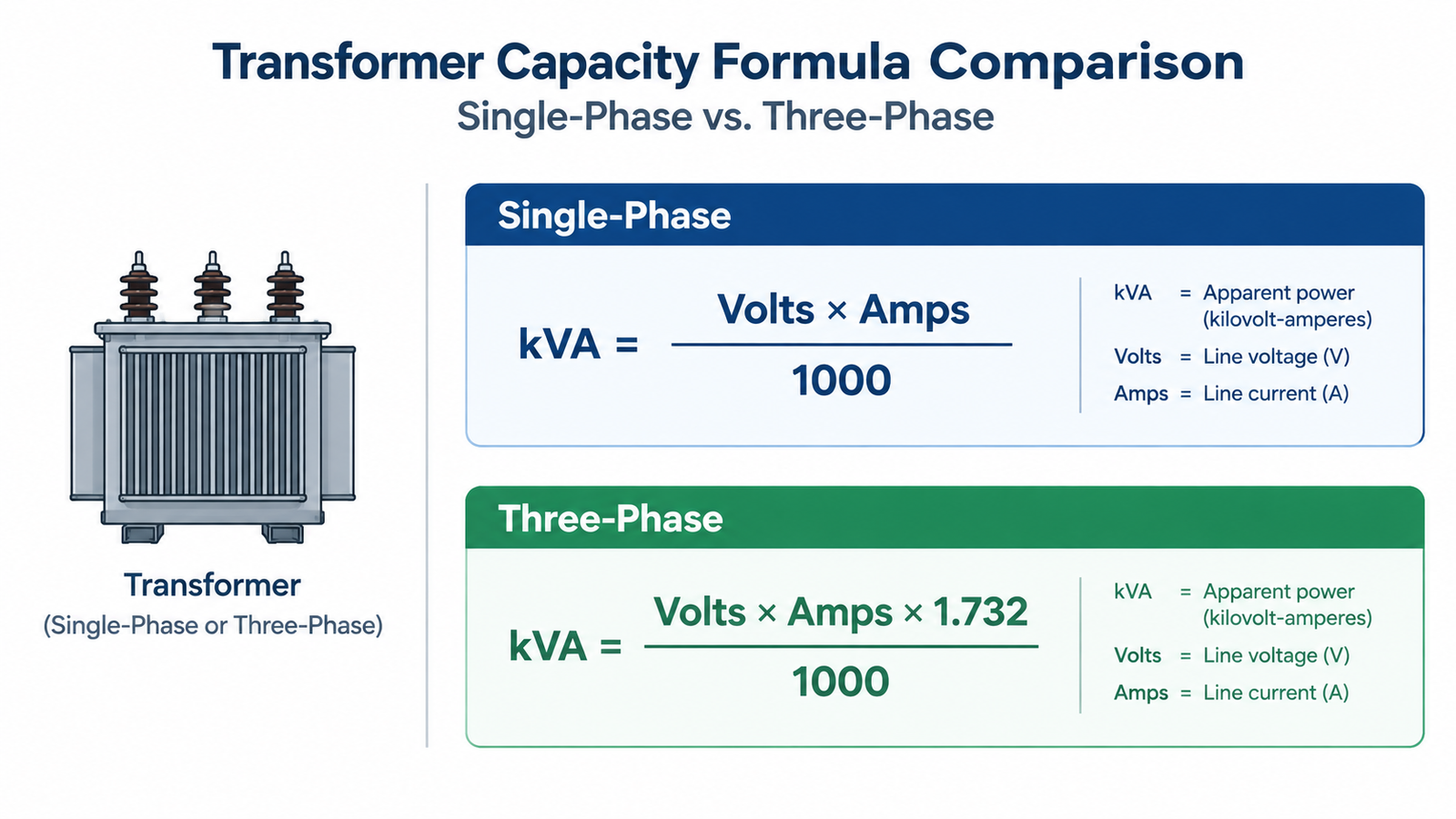
For a single-phase transformer, rated capacity is the product of the rated voltage and rated current of either winding:
kVA = (Volts × Amps) ÷ 1,000
Example: a 230 V secondary rated for 10 A gives (230 × 10) ÷ 1,000 = 2.3 kVA, and the unit would be selected from the next standard rating above this figure.
Three-phase transformer capacity
Three-phase systems carry the √3 factor because the phases share the total power:
kVA = (Volts × Amps × 1.732) ÷ 1,000
where Volts is the line-to-line voltage and Amps is the line current. Example: a 400 V three-phase supply drawing 40 A per line needs (400 × 40 × 1.732) ÷ 1,000 ≈ 27.7 kVA, so a 30 kVA unit is the practical minimum.
The Power Relationship: kW, kVAR and kVA
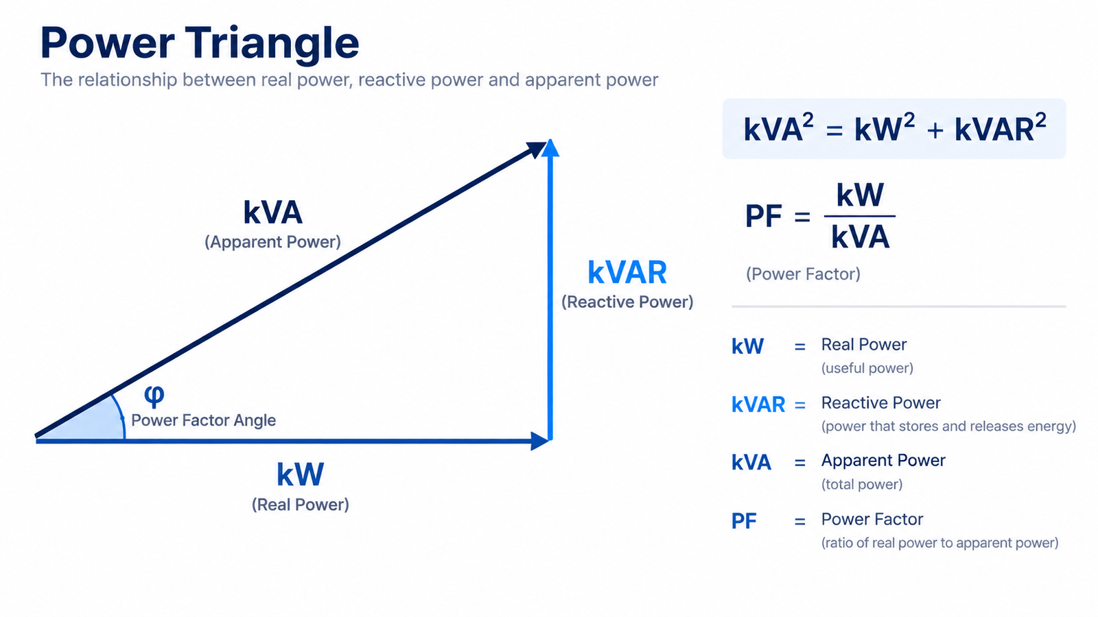
Real power (kW) does the actual work — turning motors, heating elements, lighting lamps. Reactive power (kVAR) sustains the magnetic fields of inductive loads such as motors and welding equipment; it does no useful work but still occupies transformer capacity. Apparent power (kVA) is the vector sum of the two and is what the transformer actually delivers.
These three quantities form the power triangle, in which kVA is the hypotenuse: kVA² = kW² + kVAR². The power factor (PF) is the ratio between real and apparent power: kW = kVA × PF.
This is why the same transformer supplies different amounts of real power depending on the load. A 10 kVA unit feeding a purely resistive load at unity power factor delivers 10 kW, but the same unit feeding a motor load at a power factor of 0.8 can only deliver 8 kW of useful power — the remaining 2 kVA of capacity is consumed by reactive current.
How to Calculate the Transformer Capacity Your Load Needs
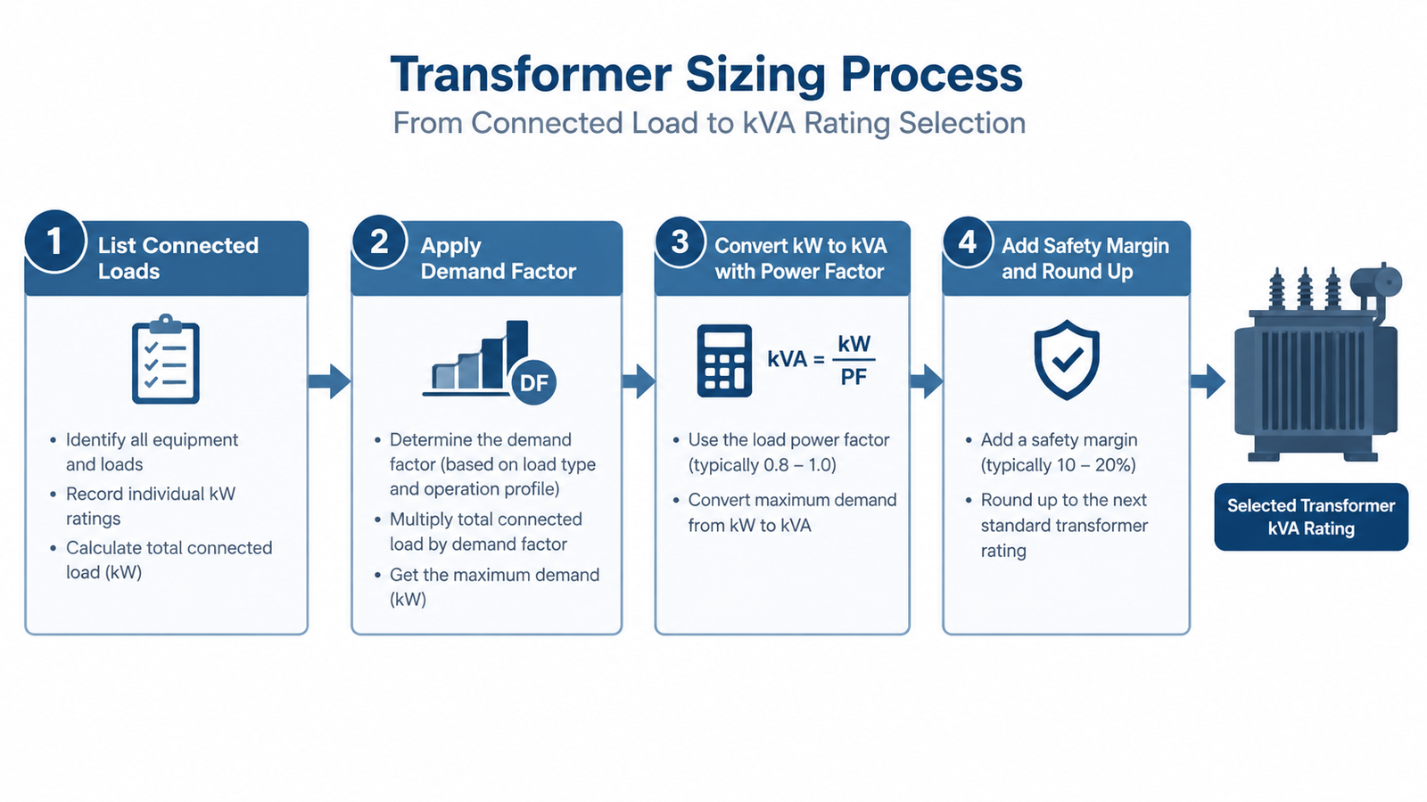
Calculating a nameplate rating from voltage and current is straightforward; sizing a transformer for a real installation takes a few more steps, because the rating must cover the worst realistic loading of the system.
Step 1 — List every connected load
Record the power of all equipment the transformer will feed: machines, motors, pumps, lighting, control systems and future additions. Where nameplates give full-load amps rather than watts, convert them to volt-amperes using the single-phase or three-phase formula.
Step 2 — Apply a demand factor
Not every load runs at full rating at the same time. Multiply the connected load by a demand factor that reflects your operating pattern — commonly 0.6–0.8 for general industrial use and closer to 0.9–1.0 for continuous process plants. For a single device this step can be skipped.
Step 3 — Convert real power to apparent power
Divide the real power in kW by the expected power factor: kVA = kW ÷ PF. If the power factor is unknown, a conservative 0.8 is a common starting assumption for mixed industrial loads.
Step 4 — Add a safety margin and round up
Add a working margin of roughly 20–25% so the transformer does not run continuously at 100% of its rating — which shortens insulation life — and so there is headroom for motor starting surges and future load growth. Then round up to the next standard rating; small control and voltage-conversion transformers are commonly manufactured in a 100 VA to 10 kVA range, so a calculated figure of 1.2 kVA would point to a 1.5 kVA unit. For guidance on operating a transformer near its limit safely, see how to calculate the overload of a transformer.
Worked Examples
Two examples show the calculation in practice.
Example 1 — Sizing a transformer for one machine
A workshop buys a 230 V machine rated at 9 A. The required capacity is (230 × 9) ÷ 1,000 = 2.07 kVA; adding 25% margin gives 2.59 kVA, so a 3 kVA unit is selected. If the machine had to run from a 110 V supply instead, the current would rise and the calculation repeated for the actual operating voltage — which is why a voltage-conversion unit such as the DT-1500VA step-up and step-down transformer is specified from the load’s real voltage and current rather than guessed from wattage alone.
Example 2 — Sizing a transformer for a small three-phase supply
A small production line draws a total of 36 kW at an estimated power factor of 0.85, giving an apparent power demand of 36 ÷ 0.85 ≈ 42.4 kVA. Applying a demand factor of 0.8 gives 33.9 kVA; a 20% margin brings the figure to about 40.7 kVA, so a 50 kVA three-phase transformer is the next standard size.
Common Transformer Capacity Mistakes
- Adding kW instead of kVA — summing watt ratings ignores reactive current and undersizes the transformer. Convert every load to VA before adding.
- Ignoring the power factor — a load list stated only in kW cannot be sized correctly unless PF is applied; the lower the PF, the larger the kVA needed for the same output.
- Checking only one side of the transformer — current is higher on the low-voltage side, so sizing from low-voltage current alone without checking the primary is a frequent error in voltage-conversion applications.
- Sizing to 100% with no margin — continuous full-load operation raises temperature rise and accelerates insulation ageing; no headroom for inrush or added equipment invites premature failure.
- Oversizing without reason — a transformer far larger than the load still incurs no-load losses every hour it is energised, so excess capacity is not free.
If your figure falls between two standard ratings, choose the higher one — but confirm the reasons rather than adding margin repeatedly. For voltage-conversion duty rather than a fixed industrial feed, browse the step-up and step-down transformer range to match a rating to your machine’s voltage and current.
Fazit
Transformer capacity calculation always comes back to one idea: capacity is measured in apparent power (kVA), because a transformer is limited by the current its windings can carry, not by the watts the load happens to use. Use kVA = (V × A) ÷ 1,000 for single-phase and kVA = (V × A × 1.732) ÷ 1,000 for three-phase systems, remember that kW = kVA × power factor, and size with a realistic demand factor plus a working margin. Applied consistently, these steps let you specify a transformer that runs cool, lasts its designed life, and leaves room for future loads.
Häufig gestellte Fragen
How do you calculate the capacity of a transformer?
Single-phase: kVA = (Volts × Amps) ÷ 1,000. Three-phase: kVA = (Volts × Amps × 1.732) ÷ 1,000, where Volts is the line-to-line voltage and Amps is the line current.
What is the difference between transformer capacity in kVA and load in kW?
kVA is apparent power — the total voltage-and-current demand the transformer must carry. kW is real power, the portion that performs useful work. They are linked by the power factor: kW = kVA × PF, so a 10 kVA transformer supplies 10 kW only at unity power factor.
How many kW can a 1500VA transformer supply?
A 1.5 kVA transformer can supply 1.5 kW at unity power factor, or about 1.2 kW at a power factor of 0.8. Leave a margin below the full rating rather than loading it continuously to the limit.
Why is a transformer rated in kVA and not in kW?
Because transformer losses and heating depend on current, which is set by apparent power (voltage × current) and is independent of the load’s power factor. Rating in kVA lets one transformer serve resistive and inductive loads alike.
What happens if a transformer is overloaded beyond its rated capacity?
Current rises above the design value, increasing I²R losses and temperature rise. Sustained overloading accelerates insulation ageing, increases voltage drop, and can eventually cause winding failure.
How much spare capacity should you leave when sizing a transformer?
Most engineers add a working margin of about 20–25% above the calculated demand to cover motor starting surges, continuous-load derating and future load growth, then round up to the next standard rating.
Recommended Models for Transformer Capacity Calculation
If you are specifying a unit rather than reading theory, start here. These models cover the capacity bands most often requested for transformer capacity calculation, and each links straight to its specification and price range.
Tell us the input voltage, output voltage, phase and continuous kVA you need, and we will confirm the matching model, price and lead time within one business day. Non-standard ratings are handled through OEM/ODM custom transformer manufacturing.