How Many Types of Transformer Are There?
A practical classification of transformer types by function, construction, cooling and application, plus a selection path for buyers.
Seguir leyendo
 Spanish
A transformer nameplate is the most reliable source of truth about a unit. The ratings printed on it define how much load the transformer can carry, which supply it may be connected to, how hot it is allowed to run, and whether it can be paralleled with another unit. Datasheets and catalogue pages are only second-hand summaries of that plate.
This guide is for the moment you are standing in front of a real unit: a new delivery to check, an old panel transformer to replace, or an imported machine whose transformador elevador y reductor has to be matched to your local supply. It walks through each field in the order it appears on most plates, explains what the number means, and flags the misreadings that cause the most field failures.
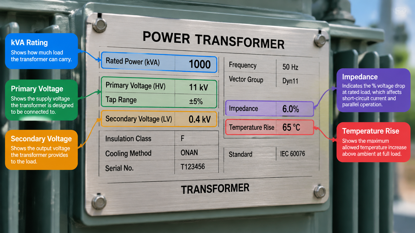
A catalogue describes a product family. The nameplate describes the unit in front of you, including the exact tap arrangement, insulation system and cooling class that were built into it. When a transformer is installed, warrantied or replaced, the serial number and printed ratings are what get checked.
Three practical tasks depend on reading it correctly: confirming the primary winding matches the available supply before energising, confirming the apparent power rating covers the real load with margin, and reproducing the electrical characteristics — not just the kVA — when the original unit is no longer available.
Everything else on the plate — impedance, losses, weight, enclosure rating, standard references — refines the picture but rarely changes a go/no-go decision.
The kVA rating is the maximum apparent power the transformer can deliver continuously at rated voltage and frequency without exceeding its designed temperature rise. It is a thermal limit expressed in electrical units: the windings are sized for a certain current, and that current is what generates the heat.

Transformers are rated in kVA rather than kW because the manufacturer cannot know your load power factor. Winding current is what heats the unit, and current depends on apparent power, not on how much of that power does useful work.
kVA = V × I / 1000kVA = √3 × Vline × Iline / 1000kW = kVA × power factorSo a 3 kVA single-phase transformer on a 230 V supply delivers roughly 13 A. At a power factor of 0.8 that is about 2.4 kW of usable power, yet the transformer is already fully loaded thermally. The reasoning is set out in more detail in why transformers are rated in kVA.
Some plates show two values, for example 1000/1333 kVA or 2.5/3 kVA. This is not a range to choose from freely — it reflects cooling stages. The lower figure applies with natural cooling (AN for dry-type, ONAN for oil-filled); the higher figure only applies when forced-air cooling is installed and running. Specifying the upper number without the fan package is a classic over-rating error. If your duty cycle includes sustained peaks, check the transformer capacity calculation as well.
Voltage is normally printed as two figures, often labelled HV and LV or PRI and SEC. The larger value is the high-voltage winding, which is not necessarily the input — a step-up transformer takes its supply on the low-voltage side.
| Printed form | What it means | Typical on |
|---|---|---|
| 230 V / 110 V | Single-phase, two windings, fixed ratio | Step-up / step-down units |
| 400 V / 230 V | Three-phase line voltage on both sides | Distribution dry-type |
| 400/230 V | One winding: 400 V line-to-line, 230 V phase-to-neutral | Three-phase four-wire |
| 0–220–240–380–415 V | Multi-tap primary, selectable by links | Control and machine transformers |
| HV: 11,000 V ± 2 × 2.5% | Off-circuit taps, four 2.5% steps around nominal | Medium-voltage units |
The slash is what trips people up. Separated by a wider gap, it divides two windings; inside a single winding value, it separates line-to-line from phase-to-neutral. If the plate shows a tap table, record the tap position actually wired on the terminal block, not the nominal figure.
Rated current is derived rather than designed: it follows from the kVA and voltage above. It is still worth recording, because it sets cable size, breaker rating and terminal requirements.
Frequency deserves more attention than it usually gets. A 60 Hz transformer run on 50 Hz draws higher magnetising current and runs hotter at the same voltage; a 50 Hz unit on 60 Hz usually survives but loses regulation headroom. On imported machinery this is a common reason a correctly sized transformer still overheats — see causes and hazards of transformer overheating. For three-phase units, the vector group (Dyn11, Yyn0) tells you the winding connection and phase shift; two transformers may only be paralleled when their vector groups are compatible.
Percent impedance is the voltage, as a percentage of rated voltage, needed to drive rated current through one winding with the other short-circuited. Typical values are 3–8% for distribution units. It does three jobs: it limits prospective short-circuit current on the secondary, it determines voltage regulation, and it governs load sharing between paralleled units.
When replacing a transformer, match impedance within roughly 10% of the original. Matching kVA alone while ignoring %Z is how a replacement ends up tripping breakers the old unit never touched.
This is where service life is decided, and it is the field most often read wrong. Three numbers appear near each other and they are not interchangeable.
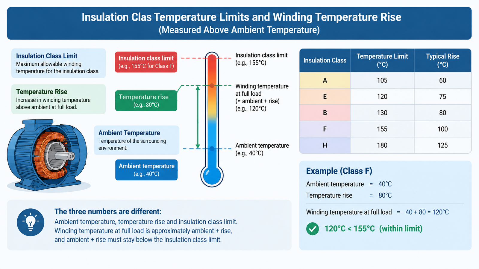
Winding temperature at full load is approximately ambient plus rise. A unit rated 40 °C ambient with an 80 K rise runs its windings near 120 °C, comfortably inside a Class F system rated 155 °C.
| Clase de aislamiento | Maximum winding temperature | Typical rise at 40 °C ambient | Common use |
|---|---|---|---|
| Class A (105 °C) | 105 °C | 55–60 K | Older oil-filled designs |
| Class B (130 °C) | 130 °C | 80 K | General dry-type |
| Class F (155 °C) | 155 °C | 100–115 K | Modern dry-type standard |
| Class H (180 °C) | 180 °C | 125–150 K | High-ambient, heavy duty |
A long-standing rule of thumb for insulation ageing is that sustained operation roughly 8–10 °C above the class limit halves expected insulation life. A temperature rise figure is therefore not a buffer to spend. In a hot enclosure, derate the load instead of accepting a higher winding temperature — the method is covered in how to calculate transformer overload.
Short letter codes carry a lot of meaning:
Rule of thumb: if the plate lists a standard you do not recognise, ask which tests were actually performed against it. A standard reference on a plate is a claim, not a certificate.
Suppose a dry-type single-phase unit carries the following:
| Field | Printed value | What you conclude |
|---|---|---|
| Rated power | 3 kVA | About 13 A at 230 V, or 27 A at 110 V |
| Tensión | PRI 0–220–240 V / SEC 110–120 V | Multi-tap primary; link position must be checked |
| Frecuencia | 50/60 Hz | Usable on either supply; regulation differs slightly |
| Fase | 1 PH | Single-phase only |
| Clase de aislamiento | Class F, 155 °C | Winding limit 155 °C |
| Temperature rise | 80 K | ~120 °C winding at 40 °C ambient, full load |
| Refrigeración | AN | No fans; the 3 kVA figure is final |
| Recinto | IP20 | Indoor, protected location only |
Read together, this unit carries 3 kVA continuously in a 40 °C room with natural ventilation, provided the primary links match the supply present. Install it in a sealed cabinet and the ambient rises, so the winding rises with it — the 3 kVA rating quietly stops being true.
| Misreading | ¿Qué ocurre? | Correct reading |
|---|---|---|
| Treating kVA as kW | Transformer runs hot at apparently “half load” | Divide kW by power factor to get kVA |
| Using the forced-air rating without fans | Chronic overload and insulation ageing | Use the AN / ONAN figure unless cooling is installed |
| Ignoring ambient temperature | Overheating in enclosures and tropical sites | Winding temperature ≈ ambient + rise |
| Matching kVA but not %Z | Nuisance tripping, poor parallel load sharing | Match impedance within ~10% |
| Assuming taps are set to nominal | Wrong output voltage on energising | Verify the wired tap position on the terminal block |
| Reading 400/230 V as two windings | Incorrect connection attempt | Slash inside one value = line-to-line / phase-to-neutral |
Once the plate is decoded, write the specification in the supplier’s language: rated power, voltages with tap range, frequency, phase and vector group, insulation class, temperature rise, cooling class, impedance, enclosure rating and applicable standard. That list is enough for an accurate quotation or a true like-for-like replacement, and it prevents the expensive mistake of buying on kVA alone. If the unit you are replacing serves 110 V equipment from a 230 V supply, our Transformador elevador y reductor ST-3000VA shows how those ratings appear on a real product plate.
If two printed values conflict with your site conditions and you need a replacement, send us a photo of the plate; the serial number alone is usually enough to retrieve the original test data.
It is the maximum apparent power the transformer can deliver continuously at rated voltage and frequency without exceeding its designed temperature rise. Convert your load’s kW to kVA by dividing by the power factor before comparing.
Insulation class is the maximum temperature the insulation system tolerates continuously, for example 155 °C for Class F. Temperature rise is how much above ambient the winding actually gets at full load. Ambient plus rise must stay below the class limit.
Not at rated voltage. The lower frequency increases magnetising current and core flux, so the transformer runs hotter and may saturate. Derating is possible but should be confirmed with the manufacturer.
They need the same voltage ratio, a compatible vector group, impedance within roughly 10% of each other, and the same polarity. Matching kVA alone is not sufficient.