A medical isolation transformer is not a different kind of winding — it is a transformer whose insulation barrier, spacing and test records have been documented against a medical safety standard. That distinction matters more than any datasheet headline, because two units with identical kVA, ratio and footprint can sit on opposite sides of a certification review. This guide explains what the label requires, how the leakage current budget is set, and what to demand from a supplier before you approve a sample. If galvanic separation itself is still new ground, start with our overview of low-voltage transformers and return here for the compliance layer.
What Makes a Transformer “Medical-Grade”?
Three properties separate a medical-grade unit from an industrial one, and all three are measurable:
- Dielectric strength across the barrier. The primary-to-secondary insulation must survive a specified AC proof test for one minute without breakdown or flashover.
- Low interwinding capacitance. Capacitive coupling across the barrier is the main path for leakage current at mains frequency, so a medical design keeps it small — often below 50 pF, against several hundred picofarads in a general-purpose unit.
- Physical separation. Creepage along surfaces and clearance through air between primary and secondary must meet a minimum distance, and that distance must survive varnish, potting and terminal routing.
Notice what is missing: a particular core shape. Toroidal cores are popular in medical supplies because they radiate less, but an EI-laminated transformer with adequate spacing, a proper insulation system and a shield meets the same electrical requirements. Our comparison of toroidal transformers and their applications covers that trade-off.
The Standards Behind the Label
Two standards families get quoted in the same conversation, and confusing them is the most common source of a failed review.
| Standard |
What it covers |
Who it applies to |
| IEC 60601-1 (and the North American ANSI/AAMI ES60601-1) |
Basic safety and essential performance of medical electrical equipment, including means of protection, leakage limits and spacings |
The finished device. The transformer is one component inside that assessment |
| IEC 61558-2-15 |
Safety isolating transformers for medical locations — the wall-mounted or floor-standing isolation units used in hospital treatment areas |
The transformer as a standalone product |
| UL 1446 / IEC 60085 |
Insulation systems and thermal classes used inside the transformer |
The winding insulation build, verified as a system rather than by single materials |
Here is the point most buyers miss: a transformer does not hold “60601 certification” on its own — the device does. What the supplier provides is a component evaluated to a defined insulation class and spacing, plus test evidence that lets your test house accept it inside the device. A supplier claiming “our transformer is IEC 60601 certified” is either describing a device-level approval or overstating a component claim. Ask which document they hold and who issued it.
Leakage Current: The Number That Sets the Design
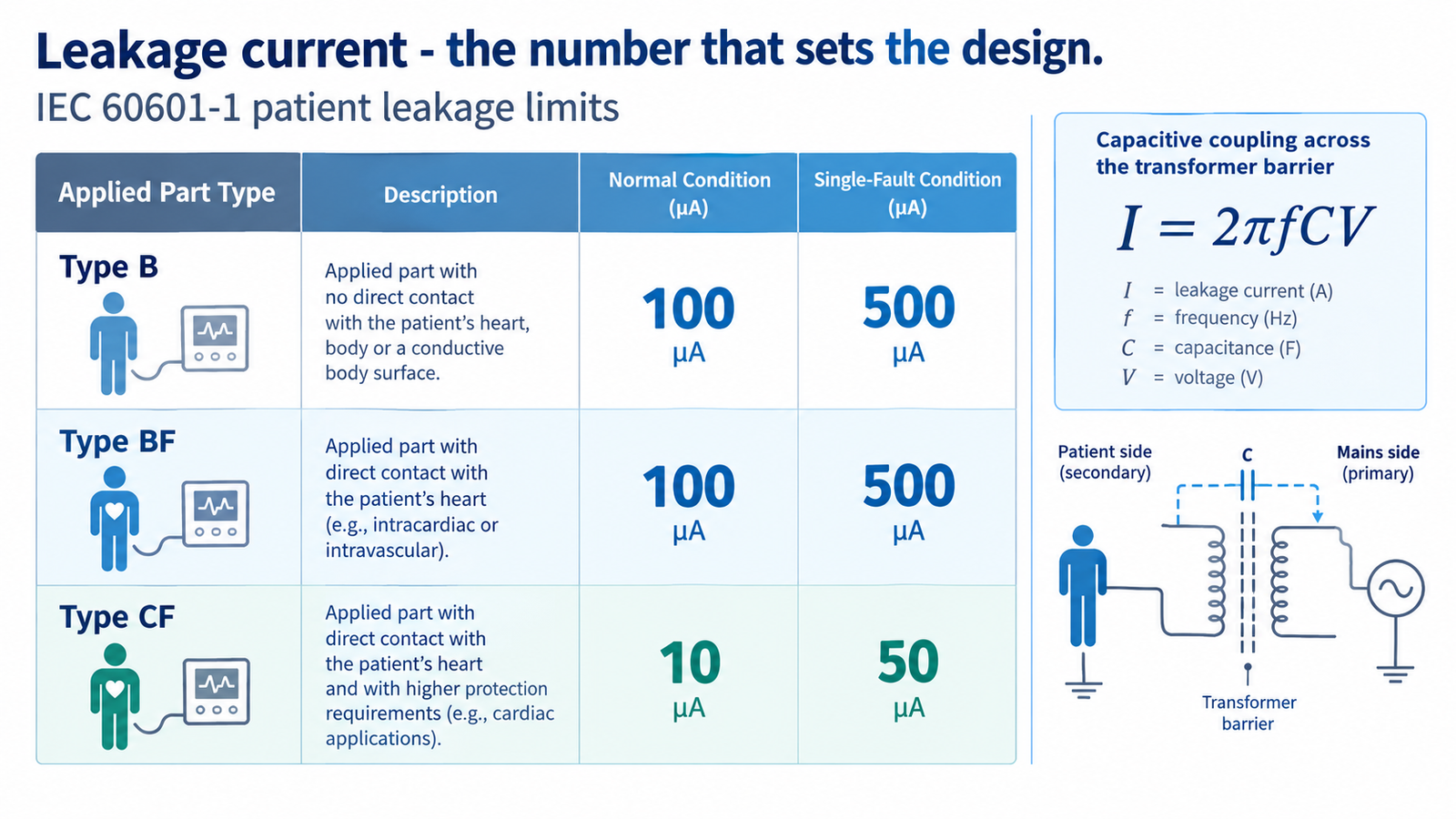
Leakage current is the reason medical isolation exists. In a normal installation, a small current flows from the live conductor through insulation and capacitive coupling to earth. In a patient-care setting, that current has a path through a person whose skin resistance may be compromised and who cannot let go of a connection. IEC 60601-1 therefore caps it by applied-part type.
| Applied part type |
Normal condition |
Single-fault condition |
Utilisation typique |
| Type B |
100 µA |
500 µA |
General monitoring, equipment with no conductive patient contact |
| Type BF |
100 µA |
500 µA |
Conductive contact with the body, floating applied part |
| Type CF |
10 µA |
50 µA |
Direct cardiac contact — catheters, intracardiac procedures |
The mechanism is simple enough to calculate. Capacitive coupling across the barrier behaves like a capacitor from primary to secondary, so the injected current follows I = 2πfCV. At 230 V and 50 Hz, every 1,000 pF of interwinding capacitance couples roughly 72 µA. A general-purpose transformer with 800 pF has therefore consumed most of a Type BF budget before the device’s own supply, Y-capacitors and enclosure contribute anything. A medical design with 40 pF couples under 3 µA and leaves room for the rest of the system.
This is why an electrostatic shield between windings does double duty. It intercepts the capacitive path and returns the current to the primary side, and it gives common-mode noise a low-impedance route that does not depend on a large Y-capacitor. For the general safety case behind isolation, see how isolation transformers improve safety and power quality.
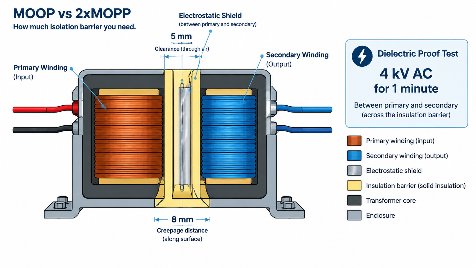
MOOP vs 2×MOPP: How Much Barrier Do You Need?
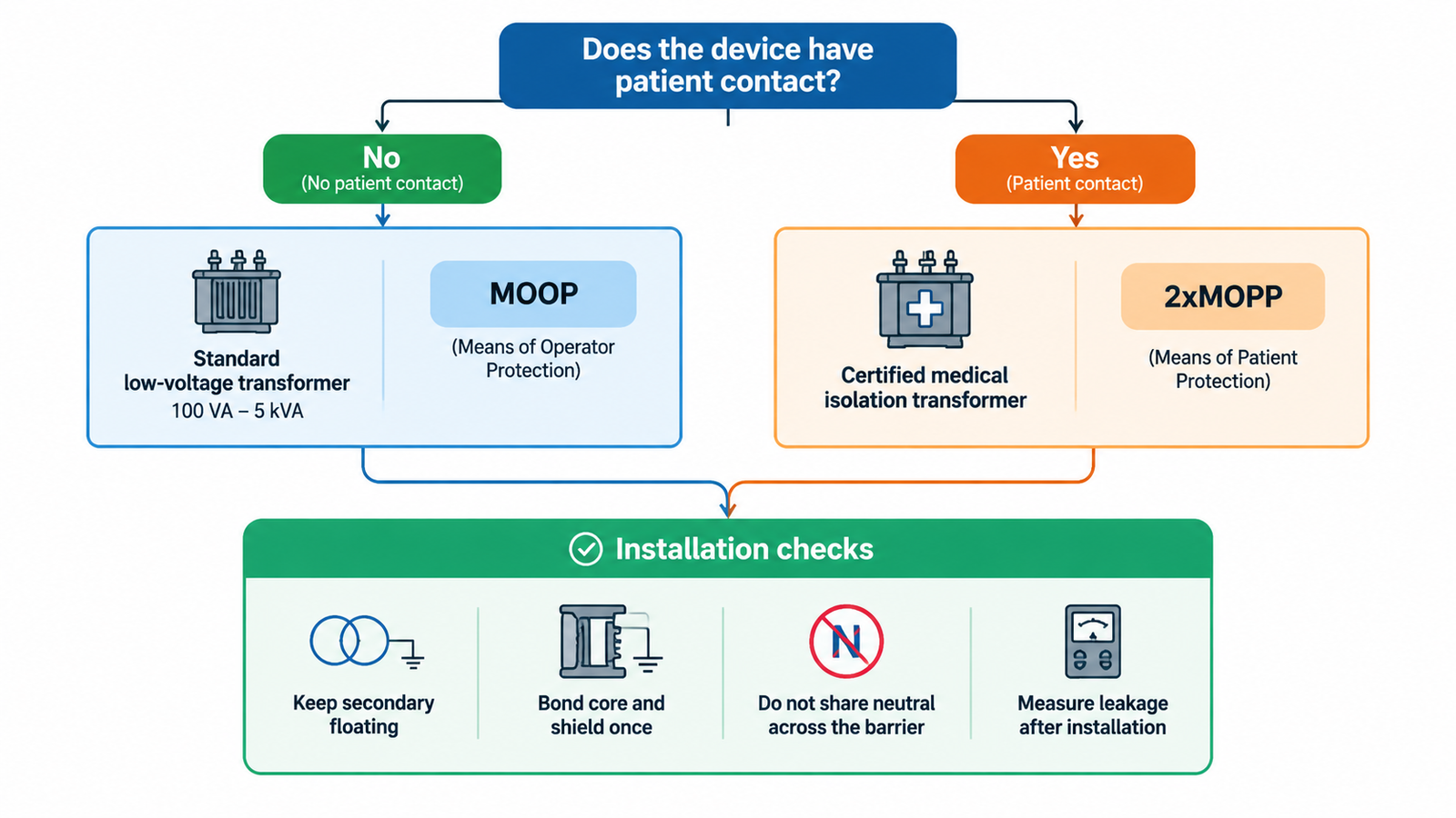
IEC 60601-1 counts protection in “means”: one means of operator protection (MOOP), or two means of patient protection (2×MOPP). Equipment that only the operator touches needs MOOP. Any patient contact needs 2×MOPP, because a patient may be unable to react to a shock and may have a low-impedance path to earth.
| Exigence |
1×MOOP |
2×MOPP |
| Dielectric proof test, 1 minute |
1,500 VAC |
4,000 VAC |
| Creepage across the barrier |
about 4 mm |
about 8 mm |
| Clearance through air |
about 2.5 mm |
about 5 mm |
| Typical insulation build |
Basic insulation plus earthing |
Reinforced or double insulation, often triple-insulated wire |
Treat those distances as indicative, not universal. Exact values depend on pollution degree, material group, altitude and the edition you certify to, and your test house has the final word. Do not assume a 4 kV test alone proves 2×MOPP compliance — spacing is checked physically, and a unit can pass hi-pot while failing creepage.
What a Standard Low-Voltage Transformer Can and Cannot Do
Most 100 VA to 5 kVA isolation and step-up units on the market are general-purpose products. Being clear about their limits saves a compliance failure later.
What a standard unit can do. It can supply equipment-side isolation where no patient-connected circuit is involved: laboratory instruments, dental and imaging support equipment whose own supply carries the medical barrier, service benches and test fixtures. It also provides a floating secondary for troubleshooting and a defined ratio for imported equipment. That is the range our STU series 100 VA–5 kVA units are built for, with fuse and MCB protection, selectable primary taps and 110–120 V / 220–240 V outputs.
What it cannot do. An off-the-shelf general-purpose transformer should not be dropped into a Type BF or CF patient circuit and called medical-grade. Its interwinding capacitance is usually too high, its creepage is not documented to 8 mm, and no per-unit hi-pot record exists. If your device has patient contact, buy a component built and tested to that requirement — or specify a custom build and get the evidence in writing.
Seven Documents to Request Before You Approve a Sample
A sample that measures correctly proves very little. The paperwork is what survives an audit.
| Document |
What it should show |
| 100% production hi-pot record |
Every unit tested at the specified voltage for the specified duration, with pass limits and a traceable serial |
| Type test report |
Dielectric, insulation resistance and temperature rise, issued by a recognised laboratory under a CB scheme or equivalent |
| Creepage and clearance drawing |
Dimensioned section through the barrier at the tightest point, not a marketing illustration |
| Interwinding capacitance figure |
Measured value in picofarads, with the test method stated |
| Insulation system and thermal class |
Class B, F or H, with the UL 1446 or IEC 60085 system reference |
| Temperature rise at rated load |
Measured rise at maximum ambient, plus the derating curve |
| Change-control statement |
Written commitment to notify you before winding, insulation or varnish changes — the usual cause of a silent compliance drift |
Sizing a Medical Isolation Transformer
Sizing follows the same logic as any low-voltage transformer, with two medical-specific twists.
Start from the continuous load in VA, not the nameplate watts of the equipment. Motors and pumps draw inrush several times their running current, and a transformer sized to the running load sags on every start. Add margin for simultaneous loads, then derate for ambient: a unit rated at 40 °C loses capacity at 50 °C, and equipment in a sealed cart runs hotter than the room. Our explanation of why transformers are rated in kVA covers the power-factor reasoning.
Two medical-specific twists. First, the transformer’s own leakage counts against the device budget, so a larger core with more winding area can be worse than a smaller, better-shielded one. Second, thermal class sets the surface temperature the enclosure must tolerate — Class B (130 °C) is common in general-purpose units, while Class F (155 °C) or H (180 °C) buys margin in a fanless cart where the unit sits close to plastic.
Installation Details That Decide Whether the Barrier Holds
A compliant transformer installed carelessly is not a compliant barrier. Three rules cover most field failures.
- Keep the secondary floating. Bond the secondary to earth and you have recreated the reference you were trying to break. The exception is a deliberately earthed secondary in a separately derived system — the bonding decision is set out in our guide to grounding a transformer secondary.
- Bond the core and shield, once. The electrostatic shield and the core need a single low-impedance connection to the protective earth of the primary side. A second bond creates a loop and can raise the very leakage you are measuring.
- Do not share neutrals across the barrier. Any conductor that crosses from secondary back to primary — a neutral, a signal ground, a USB lead — defeats the isolation completely.
After installation, measure rather than assume: earth leakage at the protective conductor, touch current at accessible metal, and patient leakage at each applied part, in normal and single-fault conditions. Record the figures — they are the baseline for every future service visit.
Common Mistakes
| Erreur |
Consequence |
| Treating “4 kV hi-pot” as proof of medical grade |
Spacing and leakage requirements are separate and are checked separately |
| Using an unshielded general-purpose unit in a BF circuit |
Interwinding capacitance alone can exceed the patient leakage limit |
| Sizing on running load only |
Voltage sag and overheating on motor inrush |
| Bonding the secondary to earth “for safety” |
Isolation is neutralised; touch current rises |
| Accepting a type-test certificate with no per-unit records |
No evidence that the shipped units match the tested design |
Conclusion
Medical-grade is a property of the documentation as much as the copper. Decide your applied-part type first, because that single choice sets your hi-pot level, your creepage and your leakage budget. Then check that the measured interwinding capacitance leaves room inside that budget, and confirm spacing on a dimensioned drawing rather than a datasheet. If your application has no patient contact, a standard 100 VA to 5 kVA isolation unit does the job honestly — just do not label it something it is not. Tell us the applied-part type, load and ambient, and we will quote against your isolation requirement rather than a generic rating.
FAQ
Is a standard isolation transformer the same as a medical-grade one?
No. Both break the conductive path, but a medical-grade unit also has documented spacing, low interwinding capacitance and per-unit dielectric test records. A standard unit can still be correct for equipment-side isolation with no patient contact.
What hi-pot voltage does a medical isolation transformer need?
Commonly 1,500 VAC for 1×MOOP and 4,000 VAC for 2×MOPP, applied for one minute at mains frequency. Confirm the figure with your test house against the edition you are certifying to, since it depends on the insulation class claimed.
Can I use a 1:1 isolation transformer for patient-connected equipment?
Only if it is a medical-grade component built to 2×MOPP and its leakage contribution fits your applied-part budget. A 1:1 ratio says nothing about insulation, capacitance or spacing.
Does a medical isolation transformer need to be earthed?
The core and any electrostatic shield must be bonded to protective earth on the primary side, once. The secondary winding should normally stay floating; earthing it turns the unit into a separately derived system and cancels the isolation benefit.
Do I need IEC 61558-2-15 or IEC 60601-1?
If you are buying a standalone isolation transformer for a medical location, IEC 61558-2-15 is the product standard. If the transformer is a component inside a medical device, the device is assessed to IEC 60601-1 and the transformer supplies part of the means of protection.