Transformer Percent Impedance (%Z): What the Nameplate Value Means
Publié le : Auteur : Lisa
Percent impedance is the one number on a transformer nameplate that tells you two things at once: how far the output voltage sags under load, and how much current the unit can push into a short circuit. On a 100 VA to 10 kVA dry-type transformer it is also the number most often missing from the plate, or copied from a datasheet written for 2,000 kVA switchgear. Here is what percent impedance measures and how to use it.
What Percent Impedance on a Nameplate Actually Means
Percent impedance, written %Z, is the fraction of rated voltage you must apply to one winding — with the other short-circuited — to drive rated current through both. A unit marked 6% needs 6% of rated primary voltage to circulate full-load current through a bolted secondary short.
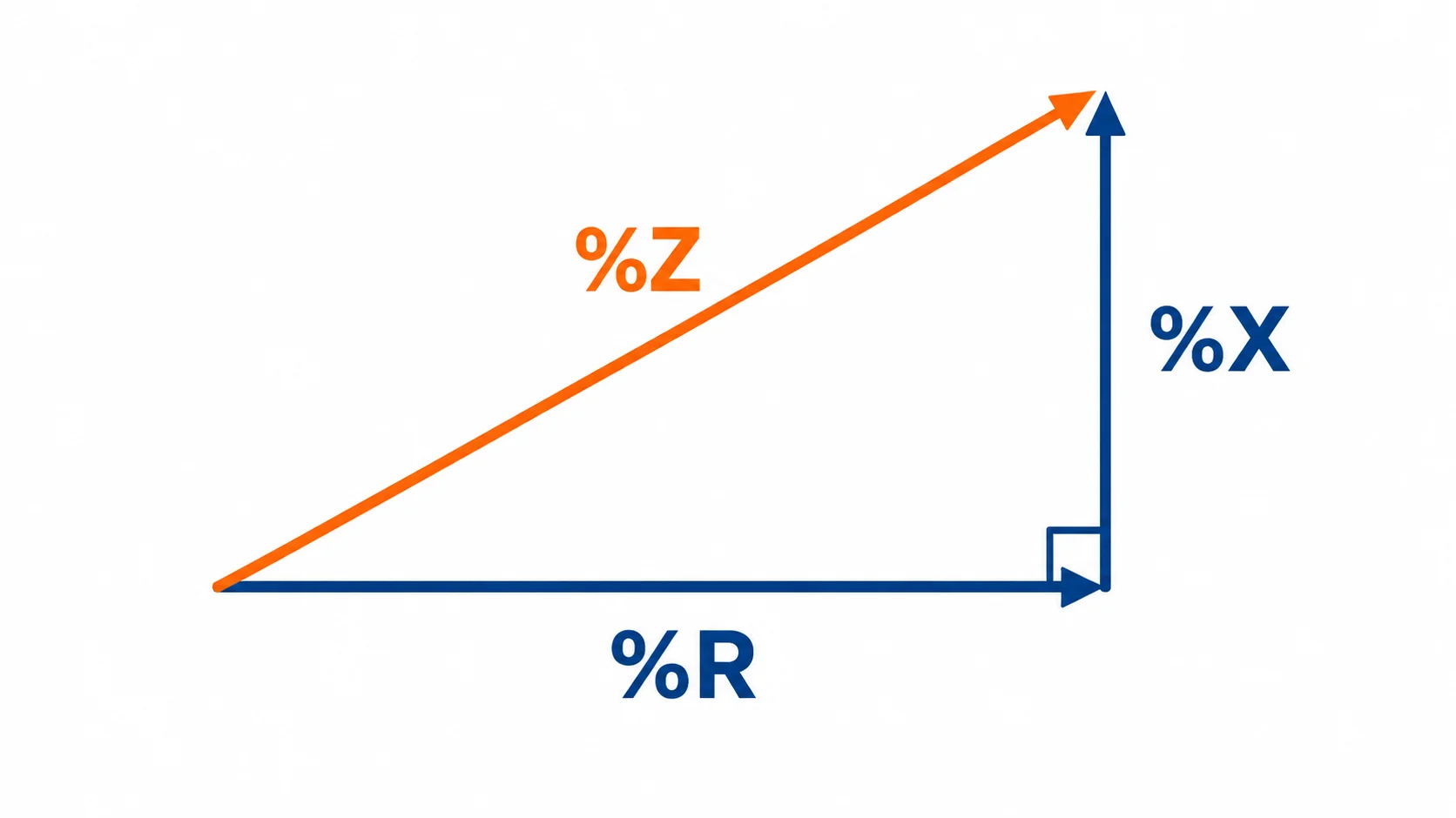
That impedance comes from two things: the resistance of the conductor, and the leakage reactance created by flux that links one winding without linking the other. The nameplate collapses both into one per-unit figure — convenient for calculation, useless for diagnosis. At small kVA ratings the split matters more than the total.
The short-circuit test behind the number
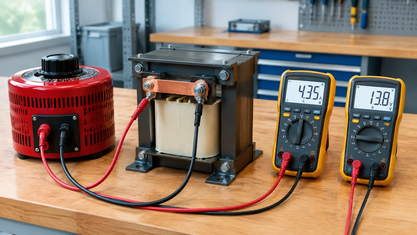
Every %Z value comes from one routine factory test. The low-voltage winding is shorted with a heavy link, a variable voltage is applied to the other winding, and the voltage is raised slowly until the ammeter reads rated current. That voltage, divided by rated voltage and multiplied by 100, is the percent impedance. The same test measures load loss. Because resistance rises with temperature, %Z is declared at a reference temperature, commonly 75 °C or 85 °C; a cold bench reading will be slightly low.
Impedance voltage, short-circuit voltage and %Z are one number
European and Asian plates print impedance voltage ou Uk; North American plates print %IZ; test reports say short-circuit voltage. Treat “Uz 4.5%” as %Z. Our guide to reading a transformer nameplate covers the neighbouring fields.
Where to Find %Z on a Small Transformer Nameplate
On a 100 VA to 10 kVA general-purpose transformer, %Z is frequently not printed at all. Standards for small transformers focus on insulation, temperature rise and dielectric strength, not on declaring impedance. Many units ship with kVA, voltage ratio, frequency, temperature rise, insulation class and a serial number, and nothing else.
Nameplate marking
What it tells you
Typical format
%Z, %IZ, IMP
Percent impedance at rated current
4.5%
Uk, Uz, impedance voltage
Same quantity, different name
Uz = 4.5%
kVA / VA
Base for rated current, which %Z is referenced to
1000 VA
Temperature rise
Thermal limit, and the reference temperature for %Z
60 K, Class F
Tap voltage
%Z is normally declared on the principal tap only
0 / +5%
If your plate has no impedance field, do not substitute a catalogue value from a similar unit — ask for the test report, or measure it.
Typical Percent Impedance for 100 VA to 10 kVA Transformers
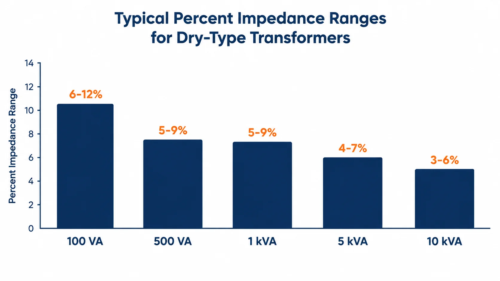
Published impedance tables start at 15 kVA, where the normal band is roughly 1.5% to 10%. Below 15 kVA there is no standard band — exactly where most small step-up and step-down buyers operate. Measured values tend to look like this:
Rating
Typical %Z
Share that is resistance
What dominates
100 – 250 VA
6 – 12%
60 – 80%
Winding resistance
500 VA – 1 kVA
5 – 9%
50 – 70%
Resistance, with growing reactance
2 – 5 kVA
4 – 7%
40 – 60%
Balanced
7.5 – 10 kVA
3 – 6%
30 – 50%
Leakage reactance starting to lead
%Z generally falls as kVA rises, because a larger core allows more turns of thicker conductor and per-unit resistance drops. More importantly, the composition flips. A 2,000 kVA distribution transformer runs at an X/R ratio of 10 to 40, so %Z ≈ %X is a fair assumption. A 500 VA transformer runs closer to X/R of 1 to 3, so much of its impedance is plain resistance that heats the winding.
What %Z Tells You About Voltage Regulation
The drop from no load to full load, in percent, is the resistance component times the power factor plus the reactance component times the sine of the power factor angle:
Vdrop% ≈ %R × cos φ + %X × sin φ
Take a 1 kVA, 230/115 V transformer with %Z of 6.0% and measured %R of 4.2%. The reactance component is √(6.0² − 4.2²) = 4.3%. At full load and a lagging power factor of 0.8, the drop is (0.8 × 4.2) + (0.6 × 4.3) = 5.9% — about 108 V on a 115 V secondary, enough to upset equipment with a ±5% tolerance. At 60% load it drops 3.5% and lands near 111 V.
Load (% of rating)
Approx. drop at 0.8 PF
Tension secondaire
0%
0%
115 V
25%
1.5%
113.3 V
50%
3.0%
111.6 V
75%
4.4%
109.9 V
100%
5.9%
108.2 V
This is why oversizing fixes most voltage complaints: a 2 kVA unit carrying 1 kVA runs at half load, so the drop halves with it. On motor loads the same impedance produces the starting dip, covered in sizing a step-up transformer for motor loads.
What %Z Tells You About Fault Current and Protection
On large transformers %Z is primarily a fault-current limiter, and the calculation is one division: rated secondary current divided by %Z in per unit.
Isc = I_rated ÷ (%Z ÷ 100)
For the 1 kVA, 115 V unit above, rated secondary current is 8.7 A and %Z is 6%, giving about 145 A. That is correct and practically misleading, because it assumes an infinite source. In a real installation the branch breaker, supply cable and source impedance sit in series with the transformer, and at this scale their combined impedance is comparable to the transformer’s own. Measured fault current on a 1 kVA unit fed from a 10 A branch is a fraction of the calculated figure.
So you do not need a short-circuit study to protect a 10 kVA transformer; you need a primary device that tolerates inrush. Small units draw a magnetising surge of roughly 10 to 20 times rated current for 10 to 100 milliseconds, so a breaker sized at rated current trips on that surge. Size the primary device at 125% to 150% of rated primary current with a C-curve or D-curve magnetic threshold above the inrush peak. %Z barely enters that decision: inrush is set by the core’s saturation flux and the point on the voltage wave where the switch closes.
%Z and Running Two Small Transformers in Parallel
Transformers sharing a bus share load inversely in proportion to their impedance. A 4% unit and a 6% unit of identical kVA will not split evenly: the 4% unit carries roughly 60% and reaches its rating first. Match impedance within about 10%, along with voltage ratio and polarity.
Nameplate matching is not enough. Declared impedance carries a tolerance band under IEC 60076-1 of roughly ±7.5% to ±10%, so two units both marked 6% can legitimately measure 5.5% and 6.5% — near the edge of the pairing window before you connect them. If parallel operation matters, compare measured values from both test reports.
How to Measure %Z on the Bench
You need a variable transformer rated for the primary current, a true-RMS ammeter in the primary circuit, a voltmeter across the primary, and a shorting link rated for the secondary current.
Disconnect the transformer and discharge any capacitance.
Short the secondary terminals with a conductor sized for rated secondary current.
Feed the primary from the variable transformer, starting at zero.
Raise the voltage slowly to rated primary current and stop — the windings dissipate load loss with almost no cooling airflow.
Read the primary voltage, divide by rated primary voltage, multiply by 100.
Power down, remove the short, and correct to the reference temperature.
Two companion tests belong in the same session. Measuring DC resistance gives you %R and lets you separate the components. A turns ratio test confirms the winding is intact first, since a displaced winding changes %Z while a shorted turn changes the ratio.
Four Ways %Z Gets Misread
Misreading
Why it happens
Correct approach
Using a 2,000 kVA catalogue value on a 1 kVA unit
Published tables start at 15 kVA and above
Measure, or use the test report
Treating %Z as %X
True for power transformers, false below about 10 kVA
Measure %R separately
Reading %Z as the voltage drop
%Z equals full-load drop only at zero power factor
Apply the %R/%X formula at the actual PF
Assuming a nameplate match means a parallel match
The tolerance band allows a ±7.5–10% spread
Compare measured values
What to Put in an RFQ
Because %Z is not a standard declaration below 15 kVA, the only way to get a usable number is to ask. State the kVA and voltage ratio, request the measured percent impedance and its reference temperature, ask for the resistance and reactance split if the load is power-factor sensitive, and require the test report with the shipment. For parallel operation, send the existing measured %Z and ask for a match within 10%.
The Practical Takeaway
Percent impedance is a voltage-drop figure first and a fault-current figure second, and at 100 VA to 10 kVA it is usually dominated by winding resistance rather than leakage reactance. Read it as the fraction of rated voltage that disappears at full load, apply the resistance and reactance split at poor power factor, and treat the fault-current formula as an upper bound, not a design value.
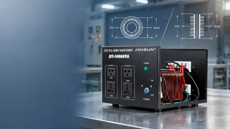
If you need impedance declared rather than assumed, our DT-1000VA step-up and step-down transformer shows the format of the data we supply, and the wider transformer range covers 100 VA to 10 kVA in single and three-phase builds. Send the load profile and we will confirm the rating that keeps the output in tolerance.
FAQ
What does 5% impedance mean on a transformer?
Applying 5% of rated primary voltage, with the secondary shorted, drives rated current through both windings. Equivalently, the unit loses about 5% of rated voltage across its own impedance at full load and near-zero power factor.
Is percent impedance the same as impedance voltage?
Yes. Percent impedance, impedance voltage, short-circuit voltage, Uk and Uz all describe the same quantity, and the percentage equals the per-unit value: 5% is 0.05.
What is a normal percent impedance for a 1 kVA transformer?
General-purpose dry-type units typically measure 5% to 9%, with half to two-thirds from winding resistance. There is no standard band below 15 kVA, so the test report is the only authority.
Can I calculate fault current from %Z alone?
Only the transformer-limited value: rated secondary current divided by %Z in per unit. That assumes an infinite source, so it overstates real fault current — dramatically below about 10 kVA.
Why is %Z missing from my transformer nameplate?
Standards covering small transformers do not require an impedance declaration. Ask for the routine test report, which carries the measured value, or measure it yourself.
A transformer cannot create cycles the supply does not have. What actually changes inside a 60Hz machine on 50Hz power, which loads genuinely do not care, and the three ways to convert frequency properly.
Gulf sites run 230/240V at 50Hz; imported US and Japanese equipment expects 110/120V at 60Hz. Sizing, wiring, ambient derating and the frequency limits of a step-down transformer, written for contractors and procurement teams.
Autotransformer advantages depend on the voltage ratio. This guide quantifies where they hold, shows the 2:1 crossover, and lists five situations where an autotransformer should not be used.