230V to 110V Transformer for Spain: REBT and Secondary Earthing
230V to 110V transformer for Spain: REBT compliance, ITC-BT-18 and ITC-BT-24, earthing the secondary and UNE-EN IEC 61558 documentation.
Read More
 English
How does a 3 phase auto transformer work? It applies three alternating voltages, separated by 120 electrical degrees, to three tapped windings that share common input and output sections. The changing current creates magnetic flux in the core, which induces voltage along each winding. By connecting the load to selected taps, the transformer delivers a higher or lower three-phase voltage while preserving the supply frequency and phase sequence.
Searches for “3 phase auto transfomer work” often lead to single-phase diagrams that do not explain what changes in a three-phase unit. The essential difference is coordination: all three phase windings must have matching ratios, polarity, and connections so the output remains a balanced three-phase set.
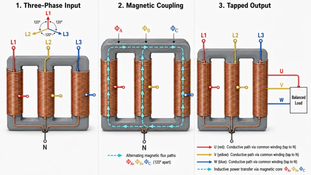
A conventional two-winding transformer transfers energy magnetically between isolated primary and secondary windings. An autotransformer uses one continuous tapped winding per phase. Because the input and output share part of that conductor, power reaches the load in two ways: part is transferred by electromagnetic induction and part is conducted directly through the common winding.
That shared path is why an autotransformer can be smaller and use less winding material for a suitable voltage ratio. It is also why the input and output are not galvanically isolated. A three phase auto transformer changes voltage; it does not generate three-phase power from a single-phase source, and it does not change 50 Hz into 60 Hz.
The source supplies L1, L2, and L3. Their sinusoidal voltages have the same frequency and nominal magnitude but are displaced by 120 degrees. Depending on the winding connection, the relevant voltage across each phase winding may be the line-to-line voltage or the line-to-neutral phase voltage.
Current in each energized winding produces alternating magnetic flux in its core limb. In an integrated three-limb core, the three fluxes interact through a common magnetic structure. In a bank arrangement, three matched single-phase units perform the same three-phase function. Balanced construction and connections help keep the output voltages symmetrical.
Faraday’s law relates the changing flux to induced voltage. For an ideal winding, voltage is proportional to the number of active turns:
Vout / Vin = Nout / Nin
If the load is connected across fewer turns than the supply, the output is lower. If it is connected across more turns, the output is higher. All three phases use the same turns ratio.
The common winding belongs electrically to both input and output circuits. Its current is the vector difference between currents associated with the source and load sections, rather than simply the full load current in every part of the coil. This sharing reduces the transformer’s internally transformed kVA when the two voltage levels are close.
Once a load is connected, current flows from the output terminals according to the load impedance and power factor. For an ideal balanced three-phase system:
S = √3 × VL × IL
Real equipment also has copper loss, core loss, leakage impedance, magnetizing current, and temperature rise. These effects influence regulation, efficiency, fault current, and the final kVA rating.
Overcurrent protection, grounding, thermal monitoring, surge protection, and correct enclosure selection help manage faults and operating stress. Because primary and secondary are electrically connected, an upstream disturbance can reach the load side. Protection must be engineered for the actual available fault current and grounding system.
A Step Up and Step Down transformer changes operating mode through the relationship between the supply terminals and output taps. The physical core and winding principle remain the same; the number of turns connected to the source versus the load determines the direction of conversion.
| Mode | Supply uses | Load uses | Electrical result |
|---|---|---|---|
| Step-down | More winding turns | Fewer winding turns | Voltage decreases and available current rises for similar kVA |
| Step-up | Fewer winding turns | More winding turns | Voltage increases and available current falls for similar kVA |
Do not assume a particular unit can be reverse-fed. Winding current ratings, taps, terminals, regulation, protection, and the manufacturer’s instructions must permit the intended direction.
Consider an ideal unit that receives 400V line-to-line and supplies 230V line-to-line. Its nominal turns ratio is:
Nout / Nin = 230 / 400 = 0.575
If it serves a balanced 50 kVA load at 230V, the ideal output line current is approximately:
Iout = 50,000 / (√3 × 230) ≈ 125.5A
The ideal input current at 400V is approximately 72.2A. Actual nameplate current and output voltage will reflect efficiency, impedance, temperature, tap selection, and load power factor. This calculation illustrates the relationship; it is not a substitute for a manufacturer’s design or installation drawing.
The construction of a 3 phase auto transformer may use an integrated laminated three-limb core or three coordinated single-phase units. Each phase has a common winding section and a series section, with taps positioned for the specified voltage ratio. Conductor area is selected for the current carried by each winding section.
A practical assembly may also include:
Voltage, capacity, frequency, enclosure, terminal layout, labels, and branding can be evaluated through JOHSUN’s ODM/OEM customization service. A complete load and installation specification is required before construction is finalized.
A 3 phase auto transformer wiring diagram shows how the three tapped windings, line conductors, output terminals, neutral, protective earth, and optional taps relate. A common arrangement is star, or wye: one end of each winding joins at a common point, and L1, L2, and L3 connect to the other ends or designated taps.
Read the diagram in this order:
Important: Continuity between input and output terminals can be normal in an autotransformer because they share a winding. Only qualified electrical personnel should install or test three-phase equipment using the supplied nameplate diagram, approved procedures, and applicable electrical rules.
A 3 phase auto transformer symbol usually shows three tapped coils or a simplified three-phase device with common winding connections. The shared coil distinguishes it from an isolation transformer symbol, which shows separate primary and secondary windings. Drawings may use Y for star and D for delta connections.
The symbol communicates function, not every installation detail. Terminal numbers, tap positions, vector relationships, neutral treatment, and grounding must come from the project drawing and the unit’s documentation.
| Selection factor | Autotransformer | Isolation transformer |
|---|---|---|
| Electrical separation | No galvanic isolation | Separate primary and secondary windings |
| Size and winding material | Often lower for close voltage ratios | Usually higher for comparable kVA |
| Efficiency and regulation | Often favorable | Depends on full magnetic power transfer |
| Typical reason to choose | Efficient voltage matching | Isolation, grounding, or noise-control requirements |
Provide input voltage and tolerance, output voltage and tolerance, frequency, kVA, load power factor, starting current, duty cycle, phase and neutral arrangement, ambient temperature, altitude, enclosure rating, cooling preference, terminals, protection, and applicable standards. Motors, rectifiers, welders, and other high-inrush or nonlinear loads require extra detail.
You can review the wider range of JOHSUN power products, learn about manufacturing capabilities on JOHSUN About, or send a complete project specification through Contact Us.
The following related products are single-phase 110/220V converters rather than three-phase models. They provide useful examples of available step-up and step-down capacities and formats:
No. The common winding creates a conductive connection between input and output. Use a suitable isolation transformer when galvanic separation is required.
No. It adjusts the voltage of an existing three-phase supply. Creating three-phase output from a single-phase source requires different conversion equipment.
No. The output frequency follows the input frequency. Frequency conversion requires a frequency converter or variable-frequency drive suited to the load.
A star connection provides a convenient common point and reduces phase-winding voltage relative to line voltage. Grounding, harmonics, balance, and system requirements still determine whether it is appropriate.
The voltage magnitude may appear correct, but connected motors can rotate in the opposite direction. Phase sequence must be verified during commissioning.
Choose one when the application requires galvanic separation, a separately derived system, specific grounding behavior, or isolation of certain disturbances.
A three phase auto transformer works by applying three phase-shifted AC voltages to coordinated tapped windings. Magnetic induction establishes the voltage per turn, while the shared winding conducts part of the power directly. The selected taps determine whether voltage rises or falls. This arrangement can be compact and efficient, but it provides no input-to-output isolation, so correct specification, protection, grounding, and professional installation are essential.