Какую роль играет трансформатор тока на подстанции? Полное руководство
Опубликовано: Автор: Лиза
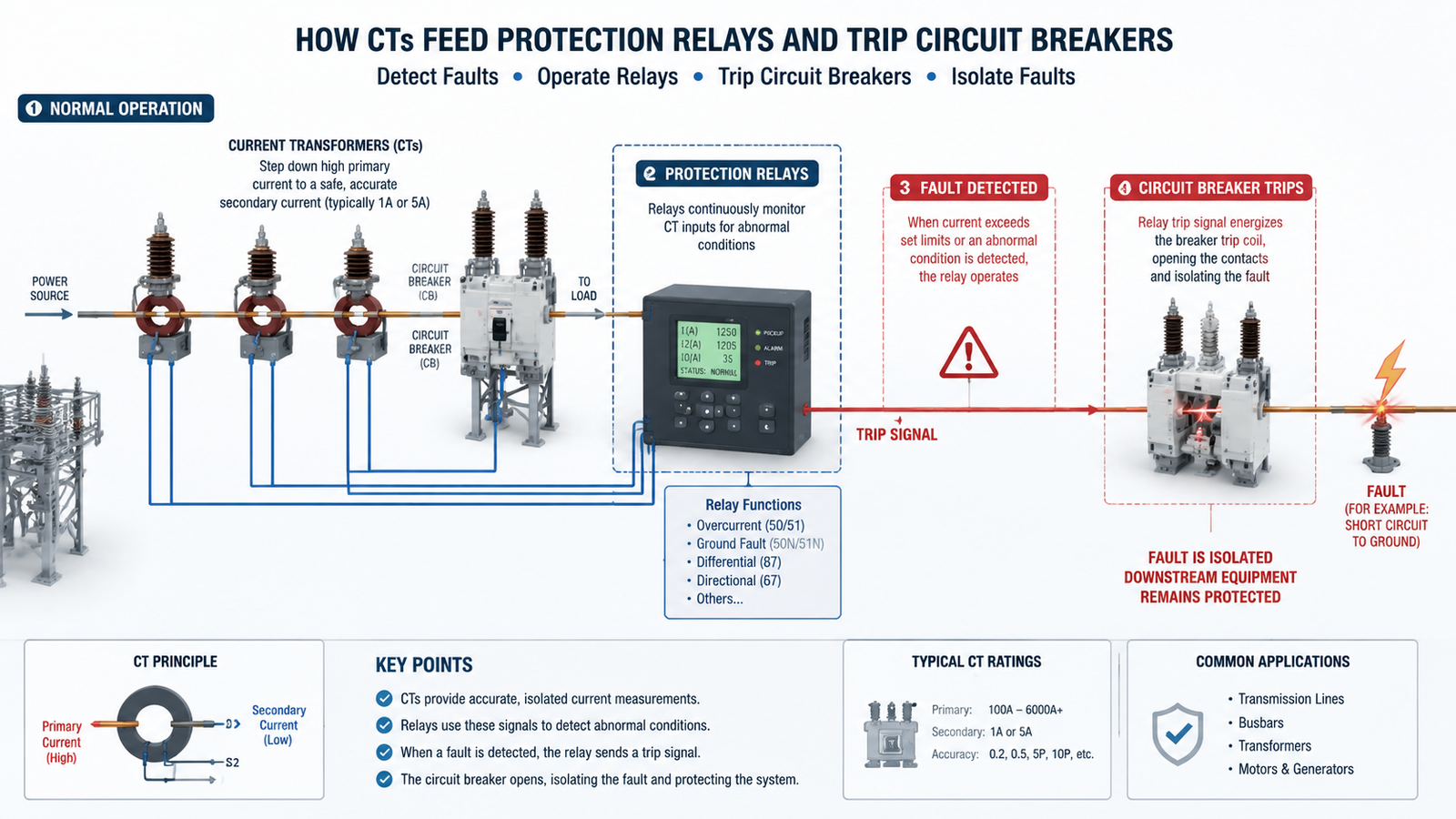
Внутри высоковольтных электрических подстанций сила тока может достигать тысяч ампер — это значения, значительно превышающие те, с которыми могут напрямую работать стандартные приборы или защитные реле. Именно здесь трансформатор тока становится незаменимым. Трансформатор тока (ТТ) понижает мощные первичные токи до безопасных стандартизированных вторичных сигналов, которые питают все — от амперметров и счетчиков энергии до реле защиты и систем SCADA.
В данном руководстве мы рассказываем, какую роль играет трансформатор тока на подстанции, как он работает, какие существуют его типы и почему правильный выбор имеет важное значение для безопасности и точности эксплуатации.
Что такое трансформатор тока?
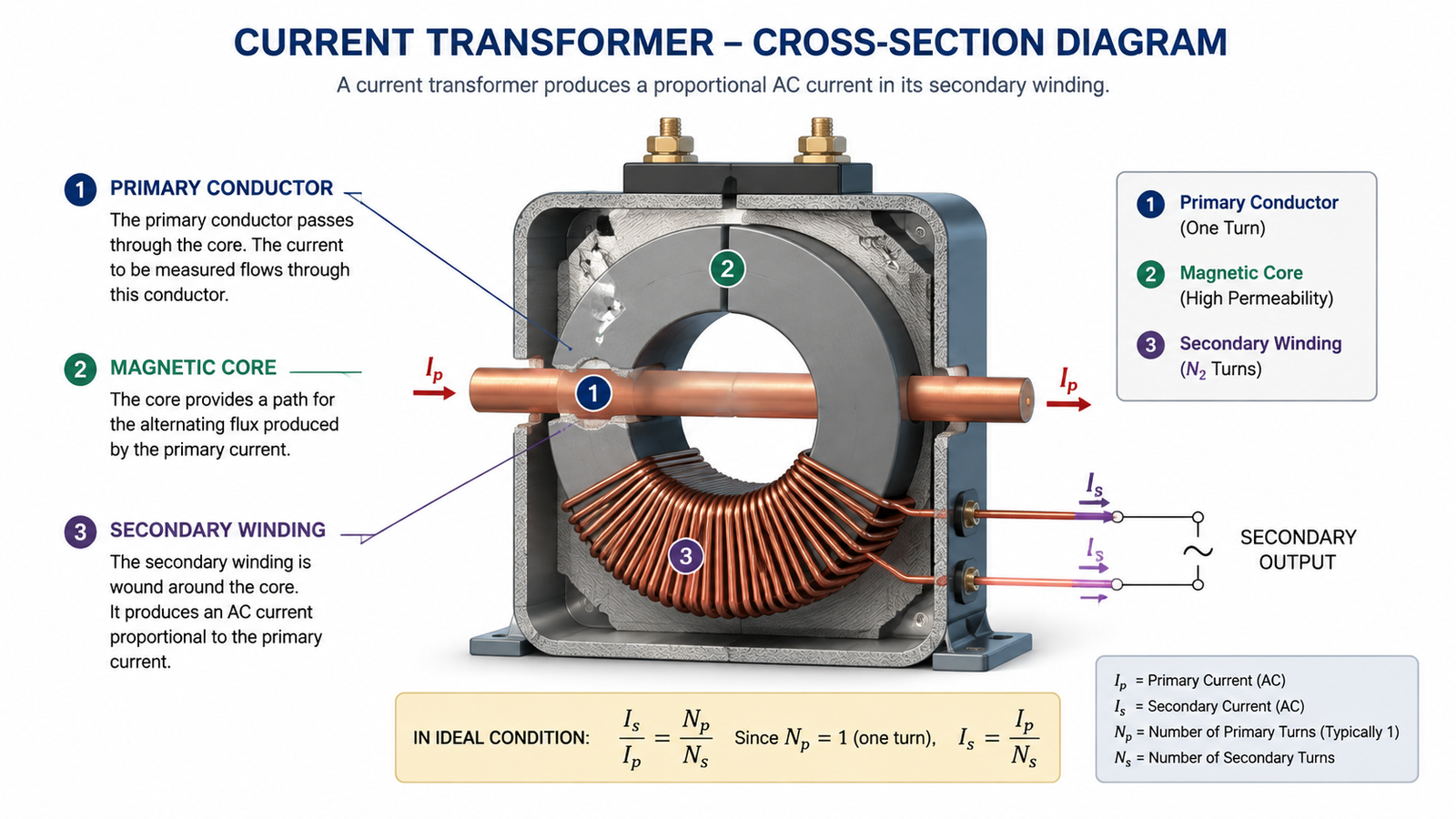
Трансформатор тока — это измерительный трансформатор, предназначенный для формирования во вторичной обмотке пропорционального переменного тока, величина которого точно соответствует силе тока, протекающего в первичной цепи. В отличие от силовых трансформаторов, которые изменяют уровни напряжения для распределения энергии, трансформаторы тока созданы для измерения и защиты, а не для передачи энергии.
Основная конструкция состоит из трёх основных компонентов:
Первичная обмотка: Часто через окно сердечника трансформатора тока проходит всего один проводник, шина или кабель.
Магнитный сердечник: Листы из высокопроницаемой кремниевой стали, которые концентрируют магнитный поток для обеспечения эффективной электромагнитной связи.
Вторичная обмотка: Сотни или тысячи витков тонкой медной проволоки, по которой к подключенным устройствам подается ток небольшой силы — как правило, 1 А или 5 А.
Коэффициент трансформации определяет масштабный коэффициент. Трансформатор с соотношением 1000:5 преобразует первичный ток 1000 А в ток 5 А на вторичной обмотке, что обеспечивает безопасную работу обычных измерительных приборов и реле при сохранении точности измерений.
Почему на подстанциях используются трансформаторы тока
Современные подстанции работают при напряжении от 11 кВ до 765 кВ и выше, при этом ток в основных цепях в нормальном режиме может превышать 10 000 А, а при аварийных ситуациях — многократно возрастать по сравнению с этим значением. Прямое подключение измерительных или защитных устройств к этим цепям нецелесообразно и небезопасно.
Трансформаторы тока решают эту задачу, преобразуя килоамперы в безопасные сигналы напряжением 1 А или 5 А, обеспечивая электрическую развязку высоковольтных первичных цепей от низковольтных вторичных измерительных приборов, а также обеспечивая равномерные вторичные токи для обеспечения совместимости счетчиков, реле и систем мониторинга. Без трансформаторов тока подстанции не смогли бы осуществлять точный расчет оплаты, быстро обнаруживать неисправности или поддерживать работу систем мониторинга в режиме реального времени, от которых зависят операторы энергосистем.
Четыре основные функции трансформаторов тока на подстанциях
Измерение и мониторинг тока
Точное измерение тока является основой работы подстанций. Трансформаторы тока подают сигналы тока с уменьшенным масштабом на амперметры, анализаторы качества электроэнергии, системы SCADA и устройства мониторинга состояния оборудования. Операторы используют эти данные для выявления перегруженных фидеров, обнаружения дисбаланса фаз, планирования графиков технического обслуживания и оптимизации рабочих характеристик системы.
Работа защитного реле
Пожалуй, наиболее важной с точки зрения безопасности функцией трансформаторов тока на подстанциях является подача точных сигналов тока на защитные реле. Эти реле постоянно контролируют электрические параметры и инициируют срабатывание автоматических выключателей при возникновении нештатных ситуаций:
Защита от перегрузки по току: Обнаруживает превышение силы тока, вызванное коротким замыканием или перегрузкой оборудования.
Защита от замыкания на землю: Выявляет непреднамеренные пути протекания тока на землю, которые могут представлять опасность для персонала или привести к повреждению оборудования.
Дифференциальная защита: Сравнивает токи, поступающие в трансформатор или зону шины и выходящие из них, с целью обнаружения внутренних неисправностей.
Защита от фазового дисбаланса: Уведомляет операторов, когда распределение нагрузки по трем фазам становится неравномерным.
Трансформаторы тока, относящиеся к классу защиты, должны сохранять точность даже в условиях серьезных неисправностей, когда ток может взлететь до 10 или 20 раз по сравнению с нормальным уровнем. Работа реле — и, в конечном счете, безопасность энергосистемы — полностью зависит от того, насколько точно трансформатор тока передает величину первичного тока во всех режимах работы.
Учёт и выставление счетов за электроэнергию
Учет энергии в коммерческих целях представляет собой еще одно важное применение трансформаторов тока. На подстанциях энергоснабжающих компаний и крупных промышленных объектах используются прецизионные трансформаторы тока для измерения объема передаваемой энергии с целью выставления счетов. Даже небольшие погрешности измерений со временем могут привести к значительным финансовым расхождениям, поэтому измерительные ТТ должны соответствовать строгим стандартам точности, таким как IEC 61869 или IEEE C57.13.
Трансформаторы тока измервательного класса отличаются от устройств защитного класса по приоритетам конструкции. В то время как в трансформаторах тока защитного класса основное внимание уделяется линейности в условиях неисправности, в трансформаторах тока измервательного класса приоритетом является минимальная погрешность коэффициента трансформации и фазового сдвига в пределах нормального рабочего диапазона нагрузки.
Гальваническая развязка и безопасность
Трансформаторы тока обеспечивают внутреннюю гальваническую развязку между первичными цепями питания и вторичными цепями управления. Такое разделение защищает персонал, осуществляющий техническое обслуживание, от опасного напряжения, предохраняет чувствительное электронное оборудование от скачков напряжения и позволяет безопасно проводить диагностику счетчиков и реле при наличии напряжения в первичных цепях. Правильное заземление вторичных цепей ТТ — как правило, в одной точке — предотвращает появление циркулирующих токов и обеспечивает безопасное рассеивание энергии при неисправностях.
Типы трансформаторов тока, используемых на подстанциях
Тип
Строительство
Типичная область применения
КТ барового типа
Цельный первичный проводник в виде сплошного стержня, являющийся неотъемлемой частью корпуса трансформатора тока
Высокоточные шинопроводы и установки распределительного оборудования
КТ раны
Первичная обмотка, физически намотанная на сердечник
Низкие диапазоны тока, требующие высокой точности
Трансформатор тока с разъемным сердечником
Шарнирный сердечник, открывающийся для монтажа вокруг имеющихся кабелей
Проекты по модернизации и временные системы мониторинга
Втулка CT
Устанавливаются на вводные муфты трансформатора или автоматического выключателя
Установки с ограниченным пространством внутри резервуаров оборудования
Катушка Роговского
Гибкая катушка с воздушным сердечником без магнитного насыщения
Цифровые подстанции и измерения с широким динамическим диапазоном
Трансформаторы тока класса защиты и класса измерения
Разграничение между классами защиты и классами измерения имеет решающее значение для правильного выбора трансформатора тока:
Трансформаторы тока измерительного класса при нормальных условиях нагрузки следует отдавать приоритет точности. К распространённым классам точности относятся 0,2, 0,5 и 1,0, где число обозначает максимальную процентную погрешность при номинальной нагрузке.
Трансформаторы тока с классом защиты отдавать приоритет линейности в условиях неисправности. Классы точности, такие как 5P10 или 10P20, указывают на то, что трансформатор тока сохраняет заявленную точность при токе, превышающем номинальный, соответственно, в 10 или 20 раз.
Компьютерные томографы класса X определяются напряжением в точке отклонения и сопротивлением обмотки, а не традиционными пределами точности, что делает их идеальным решением для схем дифференциальной защиты, где важна точная моделировка рабочих характеристик.
Использование трансформатора тока (ТТ) класса учета в целях защиты — или наоборот — может поставить под угрозу как точность расчетов, так и безопасность системы. Всегда подбирайте класс ТТ в соответствии с его назначением.
Как правильно выбрать трансформатор тока для вашей подстанции
Правильный выбор КТ предполагает систематическую оценку электрических требований, физических ограничений и приоритетов применения:
Определите диапазон силы тока в первичной обмотке: Рассчитать максимальный номинальный ток нагрузки с учетом ожидаемого запаса на рост. Для трансформаторов следует учитывать пусковые токи при включении питания.
Опишите приложение: Будут ли трансформаторы тока питать измерительные приборы, реле защиты или и те, и другие? Существуют трансформаторы тока двойного назначения, однако их использование сопряжено с компромиссами в плане точности и стоимости.
Укажите класс точности: Для учета выручки обычно требуется класс точности 0,2 или 0,5. Для общего мониторинга допускается класс точности 1,0. Для реле защиты требуется класс точности 5P или 10P в зависимости от требований к устранению неисправностей.
Рассчитать нагрузку: Суммируйте номинальные значения мощности (VA) всех подключаемых устройств, сопротивление кабеля и сопротивления контактов. Выберите трансформатор тока (CT) с номинальной нагрузкой, превышающей эту сумму как минимум на 25%.
Проверьте уровень изоляции: Номинальное изоляционное напряжение трансформатора тока должно быть равным или превышать напряжение системы в точке установки.
Учтите физические ограничения: Для трансформаторов тока барового типа требуются прямые участки проводника. Конструкции с разъемным сердечником позволяют осуществлять модернизацию без отсоединения кабелей.
Проверка соответствия стандартам: Убедитесь, что трансформатор тока соответствует применимым стандартам, таким как IEC 61869, IEEE C57.13, или местным нормативным требованиям.
Для объектов, где также требуется преобразование напряжения или стабилизация электропитания, повышающие и понижающие трансформаторы Компания Johsun Tech предлагает надёжные устройства адаптации напряжения, которые дополняют вашу инфраструктуру учёта и защиты.
Рекомендации по установке и техническому обслуживанию
Даже самый высококачественный компьютерный томограф не сможет работать должным образом, если его неправильно установить или обслуживать. Придерживайтесь следующих передовых отраслевых практик, чтобы обеспечить долгосрочную точность и надежность:
Никогда не оставляйте вторичный канал открытым: Вторичная обмотка трансформатора тока с размыканием цепи может генерировать опасные перенапряжения. Перед проведением технического обслуживания всегда замыкайте клеммы вторичной обмотки.
Заземление только в одной точке: Вторичные цепи следует заземлять в одном месте, чтобы предотвратить появление циркулирующих токов, которые искажают результаты измерений.
Выровняйте основной проводник по центру: Смещенное расположение в пределах диапазона КТ может привести к погрешностям коэффициента, превышающим 10%.
Используйте экранированные кабели: Экранированные кабели с витой парой позволяют свести к минимуму электромагнитные помехи на подстанциях с высоким содержанием гармоник.
Проводите периодические проверки: Включить проверку коэффициента трансформации, проверку полярности, измерение нагрузки и испытание сопротивления изоляции. Повторные испытания следует проводить с периодичностью 2–4 года.
Документируйте всё: Ведите точные записи о коэффициентах трансформации, классах точности и схемах подключения, чтобы сократить время ввода в эксплуатацию при будущих модернизациях.
Заключение
Трансформаторы тока являются важнейшими компонентами любой электрической подстанции, обеспечивая безопасное измерение, надёжную защиту, точное начисление оплаты и гальваническую развязку между высоковольтными силовыми цепями и низковольтными системами управления. Понимание того, какую роль играет трансформатор тока на подстанции, а также знание различий между конструкциями класса защиты и класса учета, классов точности и критериев выбора, позволяет инженерам и операторам создавать более безопасные и эффективные энергосистемы.
Если вам нужны решения по преобразованию напряжения и стабилизации питания, которые идеально дополнят инфраструктуру вашей подстанции, ознакомьтесь с обширным ассортиментом продукции компании Johsun Tech: повышающие и понижающие трансформаторы предназначен для промышленного и коммерческого использования по всему миру.
Часто задаваемые вопросы
Можно ли оставить вторичную цепь трансформатора тока разомкнутой?
Нет. Разобщённая вторичная обмотка трансформатора тока представляет собой крайнюю опасность. При размыкании вторичной цепи магнитный поток в сердечнике резко возрастает, что приводит к появлению опасно высокого напряжения на клеммах вторичной обмотки. Перед разъединением каких-либо соединений всегда необходимо замкнуть клеммы вторичной обмотки.
В чём заключается разница между трансформатором тока и трансформатором напряжения?
Трансформаторы тока измеряют ток, понижая высокие значения тока на первичной обмотке до стандартизированных значений 1 А или 5 А на вторичной обмотке. Трансформаторы напряжения (ТН) измеряют напряжение, понижая высокие значения напряжения на первичной обмотке до стандартизированных значений 110 В или 120 В на вторичной обмотке.
Как выбрать правильное соотношение КТ?
Выберите номинальный ток первичной обмотки, равный 1,2–1,5-кратной величине максимально ожидаемого тока нагрузки. Это обеспечит работу трансформатора тока в пределах диапазона точности в нормальных условиях, а также позволит выдерживать умеренные перегрузки.
Почему измерительные и защитные трансформаторы тока относятся к разным классам точности?
В измерительных трансформаторах тока приоритетом является обеспечение высокой точности коэффициента трансформации в пределах нормального диапазона нагрузки для целей выставления счетов и мониторинга. В защитных трансформаторах тока приоритетом является линейность характеристик в условиях серьезных неисправностей, когда силы тока возрастают в несколько раз по сравнению с нормальными значениями.
Используются ли трансформаторы тока на подстанциях, работающих на возобновляемых источниках энергии?
Да. Технические контроллеры (CT) широко используются на солнечных электростанциях, ветровых подстанциях и в системах аккумулирования энергии. Они контролируют выходные токи инверторов, подают сигнал на защитные реле для обнаружения неисправностей и обеспечивают контроль соблюдения сетевых норм.
Что вызывает насыщение КТ и как его можно предотвратить?
Насыщение трансформатора тока (ТТ) возникает, когда магнитный сердечник больше не способен выдерживать растущий магнитный поток, в результате чего вторичный ток перестает точно следовать за первичным током. К числу распространенных причин относятся чрезмерный ток замыкания, высокая нагрузка на вторичную обмотку и остаточный магнетизм. Меры по предотвращению включают выбор ТТ с более высокими коэффициентами предельной точности, снижение нагрузки на вторичную обмотку и обеспечение правильного расчета параметров ТТ на этапе проектирования системы.
Recommended Models for Current Transformers in Substations
If you are specifying a unit rather than reading theory, start here. These models cover the capacity bands most often requested for current transformers in substations, and each links straight to its specification and price range.
Сообщите нам требуемое входное напряжение, выходное напряжение, фазу и номинальную мощность в кВА, и мы в течение одного рабочего дня подтвердим подходящую модель, цену и срок поставки. Запросы на нестандартные технические характеристики рассматриваются через Изготовление трансформаторов по индивидуальному заказу (OEM/ODM).
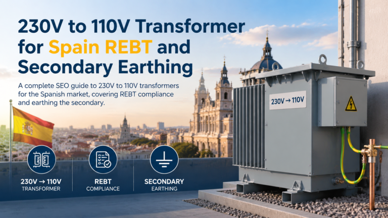
Трансформатор 230 В на 110 В для Испании: соответствие требованиям REBT, стандартам ITC-BT-18 и ITC-BT-24, заземление вторичной обмотки и документация по стандарту UNE-EN IEC 61558.
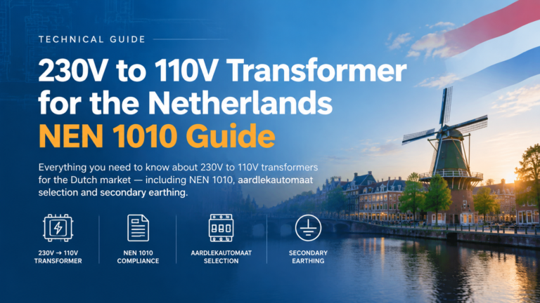
Трансформатор 230 В – 110 В для Нидерландов: стандарт NEN 1010, требования к устройствам защитного отключения (30 мА), различия между «aardlekschakelaar» и «aardlekautomaat», а также вторичное заземление.
Трансформатор 230 В — 110 В для Франции: NF C 15-100, заземление по схеме TT, дифференциальная защита на 30 мА и когда следует заземлять вторичную обмотку.
Мы используем файлы cookie для улучшения вашего пользовательского опыта, предоставления персонализированного контента и анализа посещаемости нашего сайта.