Step Up and Step Down Transformer vs Autotransformer Key Differences
Published: Author: Lisa
A conventional step up and step down transformer vs autotransformer both change AC voltage levels — but they do so in fundamentally different ways. The conventional transformer uses two electrically separate windings, providing galvanic isolation between input and output. The autotransformer uses a single shared winding, trading isolation for higher efficiency, smaller size, and lower cost. Choosing the wrong type can lead to safety hazards, damaged equipment, or unnecessary expense.
This comparison covers the key differences between a conventional step up and step down transformer and an autotransformer across construction, efficiency, isolation, cost, size, safety, and application fit — so you can make the right choice for your project.
What Is a Step Up and Step Down Transformer?
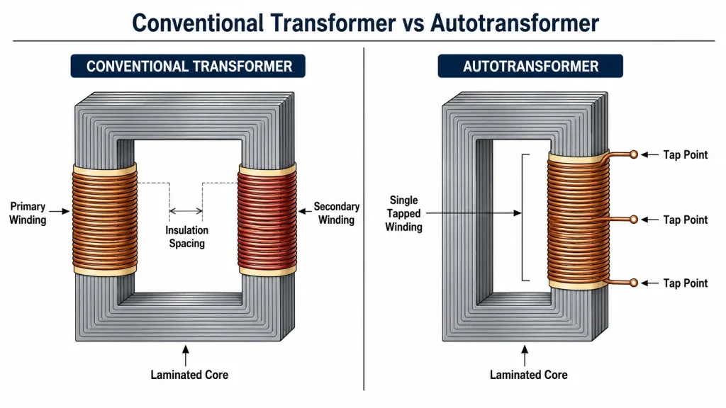
A conventional step up and step down transformer is a two-winding isolation transformer built to either increase (step up) or decrease (step down) AC voltage. It has a primary winding that receives input power and a secondary winding that delivers output power — the two are electrically separated and coupled only through a shared magnetic core.
In a step-up transformer, the secondary winding has more turns than the primary, so the output voltage is higher than the input. In a step-down transformer, the secondary has fewer turns, producing a lower output voltage. Both configurations rely entirely on electromagnetic induction — there is no direct electrical connection between the primary and secondary circuits.
These transformers are the standard choice wherever electrical isolation is required: control circuits, medical equipment, safety systems, consumer electronics, and any application where the load must be electrically separated from the supply for safety or noise rejection. To understand transformer fundamentals in more depth, see our guide on what a transformer is.
What Is an Autotransformer?
An autotransformer uses a single continuous winding that serves as both the primary and secondary. The winding has multiple tap points — by connecting the input and output to different taps, the same device can step voltage up or down. The term “auto” refers to the single coil acting upon itself, not to any automatic function.
Power transfer in an autotransformer occurs through a combination of magnetic induction (via the core) and direct electrical conduction (through the shared winding section). This dual mechanism is what gives the autotransformer its efficiency advantage: not all the power needs to be converted to magnetic flux and back. For a complete explanation of the working principle, read our article on what an autotransformer is.
Because the input and output share part of the same conductor, there is no galvanic isolation. This is the single factor that determines whether an autotransformer is suitable for a given application.
Step Up and Step Down Transformer vs Autotransformer Key Differences
The table below summarizes the core differences across the criteria that matter most in real-world selection.
Criterion
Conventional Step Up/Down Transformer
Autotransformer
Winding design
Two electrically separate windings (primary and secondary)
Single continuous winding shared by input and output
Electrical isolation
Full galvanic isolation between circuits
No isolation — input and output electrically connected
Power transfer
100% through magnetic induction
Part induction, part direct conduction
Efficiency
90%–96% typical
96%–99% typical
Size and weight
Larger and heavier for the same kVA rating
Smaller and lighter — up to 50% less material near 1:1 ratio
Cost
Higher — more copper, larger core, more manufacturing
Lower — less material and simpler construction
Safety
Safer — isolated secondary protects operators and equipment
Less safe — winding failure can expose output to full input voltage
Fault current
Lower — higher impedance limits short-circuit current
Any ratio, including very high step-up or step-down
Most economical up to ~3:1
Noise and harmonic isolation
Attenuates line-side noise and harmonics
Passes noise and harmonics through to the load
Common applications
Control panels, medical equipment, safety circuits, consumer devices
Grid interconnection, motor starting, voltage conversion, lab testing
Construction and Winding Design
The physical construction of each transformer type directly determines its electrical behavior, efficiency, and application fit.
A conventional transformer has two distinct coils wound around a laminated silicon steel core. The primary coil receives input power and creates a varying magnetic flux in the core. This flux induces a voltage in the secondary coil through Faraday’s law of induction. Because the coils are physically separated by insulation — often with a bobbin, interlayer tape, or epoxy encapsulation — there is no conductive path between them. Each winding is a continuous length of copper or aluminum wire sized for its own current rating.
An autotransformer has only one coil wound around the core, but that coil is tapped at multiple points. The portion that carries the difference between input and output current is called the common winding; the portion carrying only the primary or secondary current is the series winding. The wire gauge may change along the winding — heavier where the combined current flows, lighter elsewhere — further optimizing material use.
This single-winding construction is why an autotransformer can be built with significantly less copper and core steel for the same power rating. For a 2:1 voltage ratio, the material savings approach 50%. For a 20:1 ratio, the savings drop to about 5% — at which point the conventional design makes more sense.
Efficiency and Power Transfer
The efficiency difference between the two types comes from how power moves from input to output.
In a conventional transformer, all power must be converted to magnetic flux in the core and then back to electrical energy in the secondary winding. Every watt transferred passes through two sets of copper losses (primary I2R and secondary I2R) plus core losses (hysteresis and eddy currents). This yields typical efficiencies of 90% to 96% for well-designed units, dropping at light loads due to fixed core losses.
In an autotransformer, only the transformed portion of the power goes through the magnetic circuit. The remainder is transferred directly by electrical conduction through the shared winding — bypassing the core entirely. This means less copper loss (one winding instead of two) and less core loss (a smaller core handles the reduced magnetic load). Power autotransformers routinely achieve 98% to 99% efficiency.
The efficiency advantage is largest when the voltage ratio is close to 1:1. At a 2:1 ratio, roughly 50% of the power transfers conductively and 50% inductively. At a 10:1 ratio, only about 10% transfers conductively — and the efficiency gap narrows.
Size, Weight, and Cost
For the same kVA rating and voltage ratio, an autotransformer is almost always smaller, lighter, and cheaper than a conventional transformer. The table below illustrates the typical material difference at common voltage ratios.
Voltage Ratio (Vin:Vout)
Autotransformer Copper Saving vs Conventional
Typical Size Reduction
Cost Advantage
1.1:1 (e.g., 220V to 200V)
~90%
~80% smaller
Significant
2:1 (e.g., 240V to 120V)
~50%
~45% smaller
Large
3:1 (e.g., 360V to 120V)
~33%
~30% smaller
Moderate
10:1 (e.g., 1200V to 120V)
~10%
Minimal
Negligible
For B2B buyers and OEM projects, these material savings scale with order quantity. When the application allows it and the ratio is within practical range, the autotransformer offers a clear economic advantage.
Electrical Isolation and Safety
The most important functional difference is electrical isolation — and it determines which type is code-compliant in many scenarios.
A conventional transformer provides full galvanic isolation. There is no conductive path between the primary and secondary circuits. If a fault occurs on the primary side — a surge, short circuit, or insulation failure — the fault does not directly transfer to the secondary. The secondary can also be independently grounded according to local electrical code, creating a protected circuit for operators and sensitive equipment.
An autotransformer provides no isolation. The input and output share the same conductor. If the common winding section opens or breaks, the full input voltage can appear at the output terminals. Any surge or transient on the supply side passes through to the load. This makes autotransformers unsuitable for applications where people interact with controls, where low-voltage electronics are powered from a high-voltage line, or where electrical codes mandate isolation.
Safety standards such as IEC 61558, UL 5085, and NEC Article 450 often require isolation transformers for control circuits, medical devices, and consumer-facing equipment — precisely the applications where the autotransformer’s lack of isolation is a disqualifier.
Voltage Ratio and Application Range
Conventional transformers handle any voltage ratio. A step-up transformer can multiply voltage by factors of 10, 50, or 100 with no fundamental limitation — the secondary simply has more turns. This is why conventional transformers are used in power generation step-up (e.g., 11 kV to 400 kV), high-voltage transmission, and applications with extreme ratios.
Autotransformers are most practical at ratios up to approximately 3:1. Beyond this, the material savings become negligible, and the lack of isolation becomes harder to justify. The sweet spot for autotransformers is near-unity ratios — for example, connecting a 132 kV system to a 66 kV system, or converting between 110 V and 220 V for international equipment.
When to Choose a Conventional Transformer
A conventional step up or step down transformer is the right choice when:
Electrical isolation is required — by code, by safety policy, or by the sensitivity of the connected equipment
Operators or maintenance personnel interact with the circuit — isolation protects against shock hazards
Sensitive electronics are connected — PLCs, HMIs, measurement equipment benefit from noise and surge attenuation
The voltage ratio is large — beyond 3:1, the conventional transformer is more practical
Harmonic or noise isolation is needed — the magnetic-only coupling blocks line-side distortion
Independent grounding of the secondary is required — for separate earth references or safety earthing schemes
When to Choose an Autotransformer
An autotransformer is the better choice when:
Isolation is not required — the equipment is fully enclosed and unattended, such as motors, heaters, or sealed industrial machinery
The voltage ratio is modest — within approximately 3:1, where material savings are highest
Space and weight are constrained — portable equipment, tight enclosures, or weight-sensitive installations
Budget is a primary driver — autotransformers cost less for the same kVA rating
High efficiency is critical — applications where every percentage point of energy loss matters, such as continuous-duty systems
Variable output is needed — variable autotransformers (Variacs) provide smooth, continuously adjustable AC voltage for testing and development
Application Comparison Transformer vs Autotransformer
Application Scenario
Recommended Type
Reason
Industrial motor starter control panel (480V to 120V)
Conventional Transformer
Isolation required for operator safety and code compliance
Operating a 230V heating element on a 115V supply
Autotransformer (Step-Up)
Enclosed load, no isolation needed, compact and efficient
Medical equipment power supply
Conventional Transformer
Strict isolation requirements per IEC 60601
Interconnecting 132 kV and 66 kV transmission grids
Autotransformer
Near-unity ratio, very high power, efficiency-critical
Isolation protects CNC controller from line-side transients
Soft-starting a large induction motor
Autotransformer
Tapped reduced-voltage starting, high inrush tolerance
Consumer electronics voltage adapter
Conventional Transformer
Isolation required for consumer safety standards
The choice between a conventional step up and step down transformer and an autotransformer comes down to one question: does your application need electrical isolation? If yes, choose a conventional transformer. If not — and the voltage ratio is within practical range — the autotransformer delivers higher efficiency, smaller size, and lower cost. For help selecting the right transformer type for your project, browse our DT/ST Series product line, read our autotransformer selection guide, or contact our engineering team to discuss your requirements.
FAQ
What is the main difference between a transformer vs autotransformer?
A conventional transformer has two electrically separate windings (primary and secondary) that provide galvanic isolation. An autotransformer has a single continuous winding shared by input and output, so there is no electrical isolation. This difference affects safety, efficiency, cost, size, and which applications each type is suitable for.
Can an autotransformer replace a conventional step down transformer?
It depends on whether the application requires electrical isolation. If isolation is not needed — for example, powering a sealed motor or heating element — an autotransformer can replace a conventional transformer with higher efficiency and lower cost. If the application requires isolation for safety or code compliance, a conventional transformer must be used.
Why is an autotransformer more efficient than a conventional transformer?
In an autotransformer, only a portion of the total power transfers through the magnetic core — the rest transfers directly by electrical conduction. This reduces both copper losses (single winding instead of two) and core losses (smaller core handles less magnetic flux). Conventional transformers must transfer all power inductively, incurring losses in both windings.
Is a step up transformer the same as an autotransformer?
Not necessarily. “Step up” describes the voltage direction (output higher than input) and can apply to either type. A conventional step up transformer uses two windings with isolation. A step up autotransformer uses one tapped winding without isolation. Both increase voltage, but they differ in construction, safety, and application fit.
When should I not use an autotransformer?
Do not use an autotransformer when electrical isolation is required — for control circuits with operator interface, medical equipment, consumer electronics, safety systems, or anywhere electrical code mandates galvanic separation. Also avoid autotransformers for large voltage ratios (beyond ~3:1) where the cost advantage disappears, or in applications sensitive to line-side noise and harmonics.
Are autotransformers cheaper than conventional transformers?
Yes. For the same kVA rating, autotransformers use less copper (single winding) and a smaller core, which reduces material and manufacturing costs. The savings are largest when the voltage ratio is close to 1:1. At a 2:1 ratio, an autotransformer can cost roughly half as much as an equivalent conventional transformer.
Can I use a conventional transformer backwards as a step-up?
Technically yes — a conventional step-down transformer can be connected in reverse to step voltage up. However, this is not always recommended because the windings are optimized for a specific direction. The inrush current may be higher than expected, and the voltage regulation may be worse. It is better to use a transformer designed and rated for the intended direction of power flow.
A practical guide to grounding the secondary of small dry-type step-up and step-down transformers — which conductor to bond, how to verify it, and mistakes to avoid.
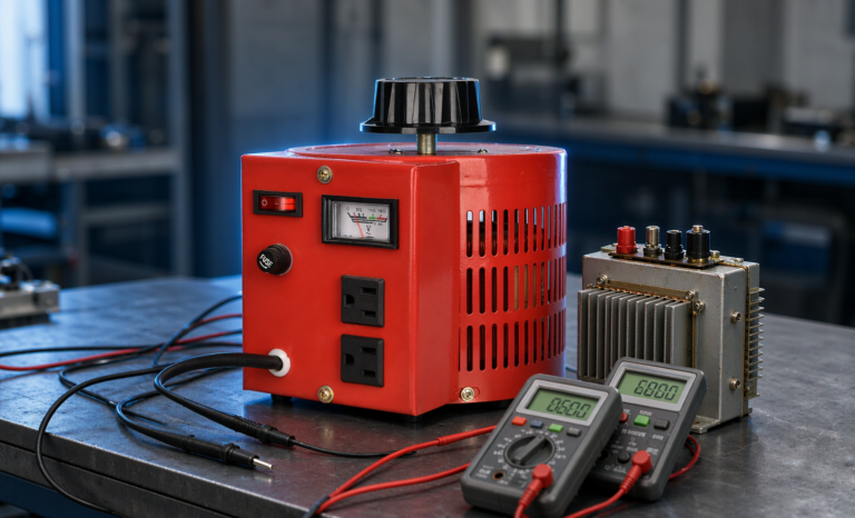
A practical guide to transformer turns ratio testing on low voltage units - the applied-voltage method with a variac, tolerance limits, tap checks, and when to call for a ratio tester.
A practical guide to measuring the DC resistance of transformer windings and motor coils, covering four-wire setup, test current selection, temperature correction and pass/fail limits.