Three-phase transformer and connection instructions
Published: Author: Johsuntech
Three-phase transformer is widely utilized for generating and transmitting electricity over long distances, primarily serving industrial and commercial needs. To adjust the voltage levels in such systems, three-phase transformers are employed, as they allow for various winding configurations to either step up or step down voltages.
Previously, we examined the construction and operation of single-phase, two-winding transformers, which can similarly modify secondary voltage levels relative to the primary supply voltage.
However, transformers are not limited to single-phase applications. They can be designed for two-phase, three-phase, six-phase, or even more complex systems, extending up to 24 phases in specialized high-power DC rectification scenarios.
By interconnecting the primary windings of three single-phase transformers and doing the same for their secondary windings in a specific arrangement, this setup becomes suitable for use with a three-phase power supply.
Three-phase supplies—denoted as 3-phase or 3φ—are essential for power generation, transmission, distribution, and industrial applications. They offer significant advantages over single-phase systems in terms of efficiency and electrical performance.
However, when working with three-phase transformers, it is important to account for the three alternating voltages and currents that are phase-shifted by 120 degrees from one another.
Three-phase transformer Three Phase Voltages and Currents
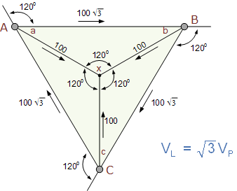
In a three-phase electrical system, the line-to-line voltage (VL) represents the voltage between any two lines, while the phase-to-neutral voltage (VP) is the voltage measured between a single phase and the neutral point. The relationship between these voltages in a star (wye) connection is given by VL=√(3)×VP.
A transformer cannot convert a single-phase supply into a three-phase supply or vice versa. To make transformers compatible with three-phase systems, their windings must be connected in specific configurations to form a three-phase transformer setup.
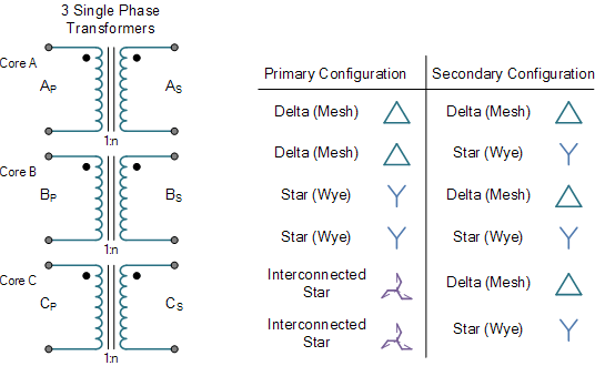
Three-phase transformer Construction A three-phase transformer can be built in two ways:
By combining three single-phase transformers to create a “three-phase transformer bank.”
By using a single, pre-assembled three-phase transformer with three pairs of windings mounted on one laminated core.
The single-unit design offers advantages such as reduced size, weight, cost, and improved efficiency for the same kVA rating compared to using three separate transformers. However, using individual transformers provides flexibility and reliability, as one unit can be replaced without affecting the entire system.
Winding Configurations Three-phase transformer windings can be connected in various configurations to meet different electrical requirements:
Star (Wye): One end of each winding is connected to form a neutral point.
Delta (Mesh): Windings are connected end-to-end in a closed loop.
Interconnected-Star (Zig-Zag): A variation of the star connection for specific applications.
The primary and secondary windings can be arranged in combinations like star-star, delta-delta, star-delta, or delta-star. Each configuration has its specific use cases:
Delta-Star (Δ-Y): Commonly used for step-up transformers at the start of transmission lines.
Star-Delta (Y-Δ): Used for step-down transformers at substations.
Star-Star (Y-Y): Suitable for high-voltage applications with balanced loads.
Delta-Delta (Δ-Δ): Ideal for low-voltage systems and unbalanced loads.
When transformers provide three or more phases, they are referred to as polyphase transformers. These configurations allow flexibility in voltage levels and ensure compatibility with different electrical systems.
Three Phase Transformer Star and Delta Configurations
In three-phase transformer systems, the terms “star” (or wye) and “delta” (or mesh) refer to specific ways of interconnecting the windings of the transformer. These configurations influence voltage levels, current flow, and system grounding.
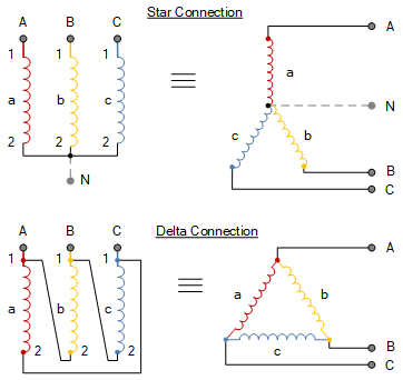
Star (Wye) Connection
In a star connection, one end of each winding is connected to a common neutral point, forming a “Y” shape. The other ends of the windings are connected to the three-phase lines.
This configuration provides both line-to-line and line-to-neutral voltages, making it versatile for systems that require multiple voltage levels. The neutral point can also be grounded for safety and stability.
In star connections, the line voltage (VL) is 33 times the phase voltage (VP), while the line current equals the phase current.
Delta (Mesh) Connection
In a delta connection, the windings are connected end-to-end in a closed loop, forming a triangle. Each corner of the triangle connects to one of the three-phase lines.
Delta connections do not have a neutral point but are reliable because they can continue operating even if one winding fails. This is particularly useful for unbalanced loads or industrial applications.
In delta connections, the line voltage equals the phase voltage, while the line current is 33 times the phase current.
Marking and Labeling
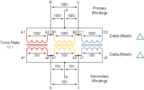
The primary windings are labeled with uppercase letters (A, B, C), corresponding to phases (e.g., red, yellow, blue). Secondary windings are labeled with lowercase letters (a, b, c).
Each winding has two terminals labeled numerically (e.g., A1 and A2 for primary windings; a1 and a2 for secondary windings).
Magnetic Flux and Phasing
When three single-phase transformers are connected in a three-phase system, their magnetic fluxes differ in phase by 120 electrical degrees. This ensures balanced operation and efficient energy transfer.
Proper phasing is critical when interconnecting windings to avoid mismatched voltages or currents.
Connection Combinations
The primary and secondary windings can be configured in various combinations:
Delta-Delta (Δ-Δ): Suitable for low-voltage systems with unbalanced loads.
Star-Star (Y-Y): Common in high-voltage systems with balanced loads.
Delta-Star (Δ-Y): Used for step-up transformers at transmission line origins.
Star-Delta (Y-Δ): Typically used for step-down transformers at substations.
These configurations allow Three-phase transformer to adapt to diverse electrical requirements while ensuring efficient power distribution.
Transformer Star and Delta Configurations
In three-phase transformer, specific symbols are employed to denote the types of connections used for both primary and secondary windings.
Connection Symbols
Uppercase Letters:
Y: Represents a star (wye) connection for the primary windings.
D: Indicates a delta connection for the primary windings.
Z: Denotes interconnected star connections for the primary windings.
Lowercase Letters:
y: Represents a star (wye) connection for the secondary windings.
d: Indicates a delta connection for the secondary windings.
z: Denotes interconnected star connections for the secondary windings.
Labeling Examples
A Star-Star (Yy) connected transformer would be labeled as Yy, indicating both primary and secondary windings are in a star configuration.
A Delta-Delta (Dd) connected transformer would be labeled as Dd, signifying that both primary and secondary windings are configured in a delta arrangement.
An Interconnected Star to Interconnected Star (Zz) transformer would be labeled as Zz, indicating that both sets of windings are interconnected stars.
These symbols provide a clear and concise way to identify the configuration of three-phase transformers, facilitating easier communication and understanding among engineers and technicians in the field.
Three-phase transformer Winding Identification
Connection
Primary Winding
Secondary Winding
Delta
D
d
Star
Y
y
Interconnected
Z
z
The four standard configurations for connecting three Three-phase transformer in a three-phase system are:
Delta-Delta (Dd)
Both primary and secondary windings are connected in a delta configuration.
Advantages:
Can operate with 2/3 capacity if one transformer fails.
Suitable for handling unbalanced loads.
Often used in industrial applications and low-voltage distribution systems.
Star-Star (Yy)
Both primary and secondary windings are connected in a star (wye) configuration.
Advantages:
Provides access to both line-to-line and line-to-neutral voltages.
Suitable for high-voltage applications.
Commonly used in power transmission systems.
Star-Delta (Yd)
Primary windings are in star configuration, secondary in delta.
Advantages:
Reduces voltage stress on primary windings.
Eliminates third harmonic currents in the secondary.
Often used for step-down transformers in distribution systems.
Delta-Star (Dy)
Primary windings are in delta configuration, secondary in star.
Advantages:
Provides a neutral point on the secondary side.
Suppresses harmonic currents in the primary.
Commonly used for step-up transformers at power generation stations.
Key Considerations
Star Configuration Benefits:
Reduces voltage stress on individual transformers.
Requires fewer turns and smaller conductors.
Easier and more cost-effective to insulate.
Particularly advantageous for high-voltage operations.
Delta Configuration Advantage:
In a delta-delta setup, if one transformer fails, the remaining two can continue to deliver three-phase power at approximately 2/3 of the original capacity.
These configurations offer flexibility in designing power systems, allowing engineers to choose the most suitable arrangement based on voltage levels, load characteristics, and system requirements.
Three-phase transformer Delta and Delta Connections
Delta-Delta (Dd) Configuration
In a delta-connected transformer group:
Line voltage (VL) equals supply voltage (VS):VL=VS
Current in each phase winding: Iphase=31×IL, where IL is the line current
Disadvantages of Delta Connection:
Each transformer must be wound for the full line voltage
Requires 57.7% of the line current capacity
Larger and more expensive coils due to more turns and insulation
No neutral or common connection available
Star-Star (Yy) Configuration
In a star-star arrangement:
Each transformer has one terminal connected to a common neutral point
The other ends of primary windings connect to the three-phase supply
Number of turns in star-connected windings is 57.7% of that required for delta connection
Characteristics of Star Connection:
Requires three transformers
If one transformer fails, the entire group may become disabled
Economical for power distribution systems
Allows for a fourth wire as a neutral point in the secondary
Advantage of Star Connection:
Enables the use of a neutral wire, which is beneficial in many power distribution scenarios
Comparison
Aspect
Delta (Dd)
Star (Yy)
Voltage
Full line voltage
57.7% of line voltage
Current
57.7% of line current
Full line current
Neutral
Not available
Available
Failure impact
Can operate at 2/3 capacity
Entire group may fail
Coil size
Larger
Smaller
Cost
Higher
Lower
Application
Industrial, unbalanced loads
Power distribution, balanced loads
The choice between delta and star configurations depends on specific system requirements, voltage levels, and load characteristics. Each has its advantages in different scenarios, making them suitable for various applications in power systems.
Transformer Star and Star Connections
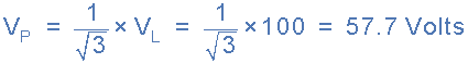
The voltage between any line of the three-phase transformer is called the “line voltage”, VL, while the voltage between any line and the neutral point of a star connected transformer is called the “phase voltage”, VP.
This phase voltage between the neutral point and any one of the line connections is 1/√3 × VL of the line voltage. Then from above, the primary side phase voltage, VP is given as.
The secondary current in each phase of a star-connected group of transformers is the same as that for the line current of the supply, then IL = IS.
Then the relationship between line and phase voltages and currents in a three-phase system can be summarised as:
Connection
Phase Voltage
Line Voltage
Phase Current
Line Current
Star
VP = VL ÷ √3
VL = √3 × VP
IP = IL
IL = IP
Delta
VP = VL
VL = VP
IP = IL ÷ √3
IL = √3 × IP
In three-phase transformer systems, VL represents the line-to-line voltage, while VP denotes the phase-to-neutral voltage on either the primary or secondary side.
Additional Three-Phase Transformer Connections
Star-Delta (Yd):
Primary winding: Star-connected
Secondary winding: Delta-connected
Delta-Star (Dy):
Primary winding: Delta-connected
Secondary winding: Star-connected
Delta-star (Dy) transformers are commonly used in low power distribution systems. They offer two key benefits:
Primary windings provide a balanced three-wire load to the utility company
Secondary windings supply the necessary fourth-wire neutral or earth connection
Turns Ratio Complexity
The overall turns ratio becomes more intricate when primary and secondary windings have different connection types (star or delta). For delta-delta (Dd) or star-star (Yy) configurations, a 1:1 turns ratio is possible, meaning input and output winding voltages are equal.
Star-Delta (Yd) Configuration Analysis
In a star-delta (Yd) connection:
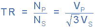
Each star-connected primary winding receives the phase voltage (VP) of the supply: VP=31×VL
The same voltage is induced in each corresponding secondary winding.
As secondary windings are delta-connected, 31×VL becomes the secondary line voltage.
With a 1:1 turns ratio, this configuration provides a 3:13:1 step-down line-voltage ratio.
This unique characteristic of star-delta transformers allows for voltage transformation without changing the number of turns, making them valuable in specific power distribution applications.
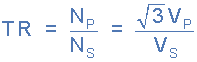
For a star–delta ( Yd ) connected transformer the turns ratio becomes:
Likewise, for a delta–star ( Dy ) connected transformer, with a 1:1 turns ratio, the transformer will provide a 1:√3 step-up line-voltage ratio. Then for a delta-star connected transformer the turns ratio becomes:
Here is a table listing the secondary voltages and currents for the four basic configurations of three-phase transformers, with respect to the primary line voltage (VLVL) and primary line current (IL):
Configuration
Secondary Line Voltage
Secondary Line Current
Delta-Delta
n×VLn×VL
IL/nIL/n
Delta-Star
3×n×VL3×n×VL
IL/(3×n)IL/(3×n)
Star-Delta
n×VL/3n×VL/3
3×IL/n3×IL/n
Star-Star
n×VLn×VL
IL/nIL/n
Where:
nn is the turns ratio of the transformer (number of secondary turns divided by number of primary turns)
VLVL is the primary line voltage
ILIL is the primary line current
This table summarizes how the different configurations affect the voltage and current relationships between the primary and secondary sides of three-phase transformers.
Where: n equals the transformers “turns ratio” (T.R.) which is the number of secondary windings NS, divided by the number of primary windings NP. ( NS/NP ) and VL is the line-to-line voltage with VP being the phase-to-neutral voltage.
Three-phase transformer Example
For a delta-star (Dy) connected transformer with the given specifications, we can calculate the secondary side voltages and currents as follows:
Turns Ratio
The turns ratio (n) is calculated as:
n = Secondary turns / Primary turns n = 100 / 500 = 0.2
Secondary Line Voltage
For a delta-star transformer, the secondary line voltage is given by:
Secondary Line Voltage = √3 × n × Primary Line Voltage Secondary Line Voltage = √3 × 0.2 × 100 V Secondary Line Voltage ≈ 34.64 V
Secondary Line Current
The secondary line current can be calculated using the transformer rating:
Secondary Line Current = Transformer Rating / Secondary Line Voltage Secondary Line Current = 50 VA / 34.64 V Secondary Line Current ≈ 1.44 A
Secondary Phase Voltage
In a star-connected secondary, the phase voltage is:
Secondary Phase Voltage = Secondary Line Voltage / √3 Secondary Phase Voltage ≈ 34.64 V / √3 ≈ 20 V
Secondary Phase Current
In a star-connected secondary, the phase current is equal to the line current:
Secondary Phase Current ≈ 1.44 A
Therefore, for this delta-star (Dy) connected 50 VA transformer:
Secondary Line Voltage: 34.64 V
Secondary Line Current: 1.44 A
Secondary Phase Voltage: 20 V
Secondary Phase Current: 1.44 A
Then the secondary side of the transformer supplies a line voltage, VLINE of about 35v giving a secondary phase voltage, VPHASE of 20v at 0.834 amperes.
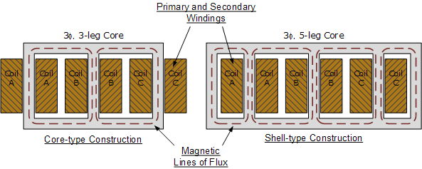
Three Phase Transformer Construction
Three-phase transformer indeed combine three single-phase transformers into one unit, offering significant advantages in terms of cost, size, and weight. This design approach results in a more compact and efficient transformer types. Let’s explore the key aspects of three-phase transformer construction:
Core Construction
Core-type Transformer
Three magnetic circuits are interlaced on a single laminated iron-core.
This design ensures uniform distribution of dielectric flux between high and low voltage windings.
Provides better magnetic coupling and reduced leakage flux.
Shell-type Transformer
An exception to the interlaced design.
Three cores are placed together but remain non-interlaced.
Often used in high-power applications due to its mechanical strength.
Advantages of Combined Design
Cost Reduction: Fewer materials required compared to three separate transformers.
Size Reduction: Compact design takes up less space in substations or industrial settings.
Weight Reduction: Lighter overall weight, facilitating transportation and installation.
Improved Efficiency: Better utilization of core material leads to reduced core losses.
Balanced Operation: Ensures more symmetrical operation in three-phase systems.
Flux Distribution
In core-type transformers, the interlaced design promotes uniform flux distribution.
This uniform distribution minimizes magnetic imbalances and reduces harmonics.
Winding Arrangement
Windings are typically arranged concentrically around the core limbs.
High-voltage and low-voltage windings are placed to optimize insulation and cooling.
The integration of three single-phase transformers into one three-phase unit represents a significant advancement in transformer design, offering a more efficient and economical solution for three-phase power systems.
Core-Type Three-Phase Transformer
The three-limb core-type design is the most prevalent method for constructing three-phase transformers. This design offers several advantages:
Magnetic Interlinking: The phases are magnetically interconnected, allowing for efficient flux distribution.
Flux Path: Each limb’s magnetic flux uses the other two limbs as its return path, creating a closed magnetic circuit.
Phase Displacement: The magnetic fluxes in the core, generated by line voltages, are 120° apart in time-phase.
Sinusoidal Output: This phase displacement results in a nearly sinusoidal flux in the core, inducing a sinusoidal secondary voltage.
Shell-Type Five-Limb Transformer
While less common, the shell-type five-limb transformer design has specific applications:
Construction: Generally heavier and more expensive to build than core-type.
Application: Commonly used for very large power transformers.
Advantage: Can be constructed with reduced height, beneficial in certain installations.
Similarities: Core materials, electrical windings, steel enclosure, and cooling systems are similar to large single-phase transformers.
Comparison
Aspect
Core-Type (Three-Limb)
Shell-Type (Five-Limb)
Common Use
Most prevalent
Large power transformers
Magnetic Coupling
Highly efficient
Efficient, but more complex
Size
Compact
Larger, but can be shorter
Cost
More economical
More expensive
Flux Distribution
Uniform across phases
More complex path
The choice between core-type and shell-type designs depends on specific application requirements, including power rating, installation constraints, and economic factors.
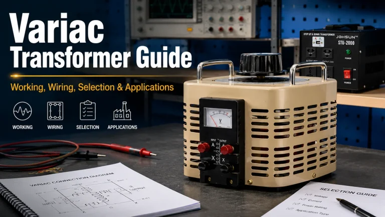
A comprehensive variac transformer guide covering construction, brush mechanism, terminal wiring, comparison with dimmers and tap changers, selection criteria, maintenance, and safety rules.
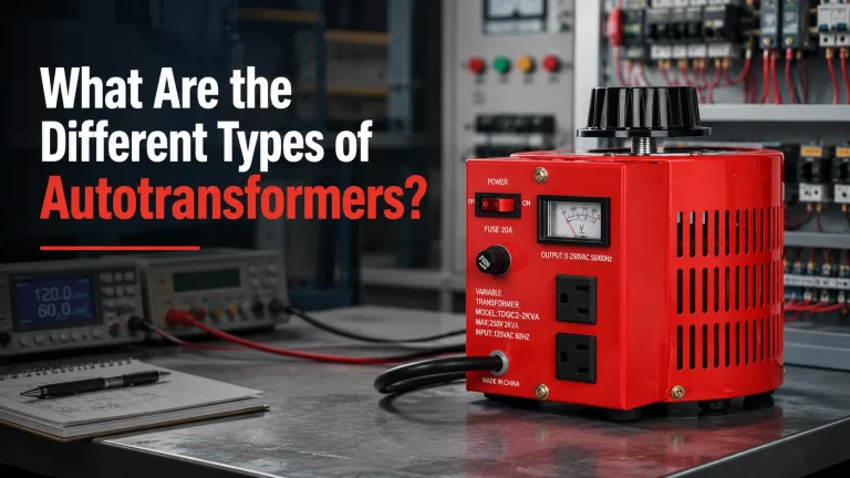
A complete classification guide covering autotransformer types by voltage function, control method, number of phases, core design, and application — with comparison tables, an 8-type summary chart, and a 5-step selection process.
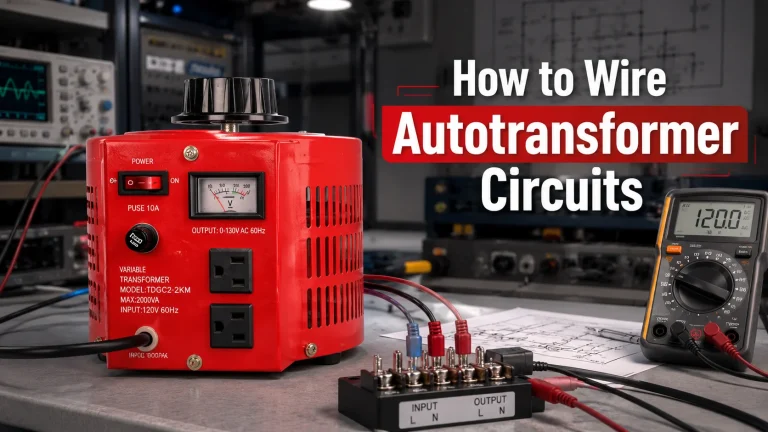
A practical wiring guide covering step-up, step-down, variable, and three-phase autotransformer circuit configurations with terminal identification charts, common mistakes, and testing procedures.