The transformer construction and iron core structure, a vital component in transformer construction, creates a magnetic circuit for field flow. This path is essential for voltage induction between input and output windings.
Traditional designs with windings on separate limbs suffer from inefficiencies due to poor magnetic coupling and significant flux leakage. However, various construction types aim to address these issues, resulting in more compact and efficient transformers.
Improving Efficiency
Enhancing transformer efficiency involves:
- Bringing windings closer together
- Concentrating the magnetic circuit around coils
While these methods improve magnetic coupling, they can increase core losses.
Core Design Considerations
The core serves two primary functions:
- Providing a low reluctance path for the magnetic field
- Preventing circulating electric currents (eddy currents) within the iron core
Eddy currents, induced by alternating magnetic fields, cause heating and energy losses, reducing transformer efficiency.
Core Construction
To minimize power losses, transformer cores are typically built using:
- Thin silicon steel laminations
- High-permeability materials
- Lamination thickness ranging from 0.25mm to 0.5mm
These laminations are assembled to create the required magnetic path while minimizing losses. The steel’s high resistivity helps reduce eddy current losses.
Insulation
To prevent electrical conductivity between laminations:
- A thin coating of insulating varnish is applied
- Alternatively, an oxide layer is used on the surface
This insulation extends to any fixing components such as studs, rivets, or bolts.
Transformer construction naming typically reflects how the windings are arranged around the central steel core. Two fundamental designs stand out: the Closed-core and Shell-core Transformers.
In this design, primary and secondary windings encircle the core ring externally. Key features include:
- Windings split between core legs
- Alternating primary and secondary coils on each leg
- Concentric arrangement for improved magnetic coupling
- Some leakage flux occurs outside the core
This type features windings passing inside the magnetic circuit. Characteristics include:
- Core forms a shell around the windings
- Primary and secondary coils on the central leg
- Central leg has double the cross-sectional area of outer limbs
- Two closed magnetic paths external to the coils
Magnetic Flux Considerations
Both designs aim to keep magnetic flux within the core, minimizing air losses. The shell-type construction offers advantages:
- Reduced leakage flux
- Decreased core losses
- Enhanced overall efficiency
In shell-type transformers, magnetic flux in outer limbs equals Φ/2, where Φ represents total flux.
Winding Arrangement
- Core-type: Half of each winding on each leg, layered concentrically
- Shell-type: Both windings on the central leg
This careful arrangement in both designs maximizes magnetic coupling, ensuring most magnetic lines of force pass through both primary and secondary windings simultaneously.
Transformer winding techniques involve careful arrangement of coils around laminated iron or steel cores. The process begins with winding coils on formers, which can have cylindrical, rectangular, or oval cross-sections to match the core’s construction.
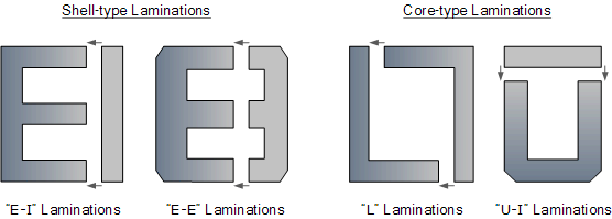
Lamination Shapes
For both shell and core type transformers, laminations are created from larger steel sheets. These are stamped or punched into specific shapes:
- “E” shapes
- “L” shapes
- “U” shapes
- “I” shapes
Core Assembly
Laminations are combined to form the desired core shape. For example:
- Shell-type transformer: Two “E” stampings + two “I” stampings = E-I core
During assembly, laminations are tightly fitted to minimize air gaps at joints, resulting in high magnetic flux density.
Stacking Technique
Laminations are stacked alternately, creating overlapping joints. This method offers two key benefits:
- Reduced flux leakage
- Decreased iron losses
More lamination pairs are added to achieve the required core thickness.
Applications
E-I core laminated transformer construction is commonly used in:
- Isolation transformers
- Step-up transformers
- Step-down transformers
- Auto transformers
This versatile design allows for efficient power transformation across various applications, balancing factors such as magnetic coupling, core losses, and overall transformer efficiency.
Transformer windings are crucial components in transformer construction, serving as the main current-carrying conductors wound around the core’s laminated sections. In a single-phase two-winding transformer, there are two distinct windings:
- Primary winding: Connected to the voltage source, creating magnetic flux
- Secondary winding: Experiences induced voltage due to mutual induction
- Step-down Transformer: Secondary output voltage < Primary input voltage
- Step-up Transformer: Secondary output voltage > Primary input voltage
Winding Materials
Two main materials are used for transformer windings:
- Copper:
- Higher mechanical strength
- Smaller conductor size
- Used in small kVA power and voltage transformers
- Results in heavier transformers
- Aluminum:
- Lighter and generally less expensive
- Requires larger cross-sectional area
- Used in larger power transformer applications
Winding Classifications
- Concentric Coils:
- Common in core-type transformers
- Higher voltage primary winding wound over lower voltage secondary winding
- Sandwiched (Pancake) Coils:
- Flat conductors wound in spiral form
- Arranged in interleaved discs
- More common in shell-type core construction
- Helical (Screw) Windings:
- Used in low voltage, high current applications
- Large cross-sectional rectangular conductors
- Wound continuously along cylinder length
- Resembles a corkscrew
Insulation
- Air-cooled transformers: Thin layer of varnish or enamel
- Larger power and distribution transformers:
- Oil-impregnated paper or cloth
- Immersed in protective tank with transformer oil
- Oil serves as both insulator and coolant
These various winding types and insulation methods allow for efficient and safe operation of transformers across a wide range of applications and power requirements.
The orientation of transformer windings is crucial for proper phase relationships between primary and secondary voltages and currents. This orientation is tracked using the “dot convention.”
Dot Convention
- Identifies the relative orientation of primary and secondary windings
- Determines the phase relationship between voltages and currents
Winding Configurations
- Dots on same side:
- Secondary current in-phase with primary current
- Voltages at dotted ends are in-phase
- Dots on opposite sides:
- Secondary current 180° out-of-phase with primary current
- Voltages at dotted ends are out-of-phase
Importance of Polarity
- Critical for transformers with multiple secondary windings
- Allows for series-aiding (voltage summed) or series-opposing (voltage difference) connections
Voltage Control
Adjusting turns ratio helps compensate for:
- Variations in primary supply voltage
- Transformer regulation
- Varying load conditions
Tapping method:
- Typically done on the high voltage (primary) side
- Lower volts per turn make adjustments easier
Tapping Example
- Calculated for ±5% supply voltage change
- Can be designed for any desired range
Multiple Windings
Some transformers feature:
- Multiple primary windings
- Multiple secondary windings
This design allows for different voltage outputs from a single core, increasing versatility.
Understanding winding orientation and polarity is essential for proper transformer construction and application, ensuring correct voltage and current relationships between primary and secondary sides.
Core Losses
The core of a transformer, typically made from iron or steel, plays a crucial role in its efficiency due to its magnetic properties. Two key concepts are important here:
Permeability
- Measures a material’s ability to support magnetic flux
- Low carbon steels have high permeability
- Permeability of steel: ~1500
- Permeability of air: 1.0
- Steel cores can carry magnetic flux 1500 times better than air
Despite the advantages of steel cores, they introduce two types of losses:
- Eddy Current Losses
- Hysteresis Losses
These losses occur when magnetic flux flows through the steel core, affecting the transformer’s overall efficiency. Understanding and minimizing these losses is crucial in Transformer construction design and construction to optimize performance.
Hysteresis Losses
Transformer Hysteresis Losses are a significant factor in transformer efficiency and operation. These losses arise from the core’s magnetic properties and the alternating nature of the electrical supply.
Cause of Hysteresis Losses
- Molecular friction against changing magnetic lines of force
- Magnetization direction changes with sinusoidal supply voltage
- Results in heat generation within the core
Effects of Hysteresis Losses
- Energy loss in the transformer
- Heat generation
- Can degrade insulating materials over time
- Necessitates effective cooling strategies
Frequency Dependence
Transformers are designed for specific operating frequencies. Altering the supply frequency impacts hysteresis losses:
- Lowering frequency (e.g., 60 Hz to 50 Hz) leads to:
- Increased hysteresis
- Higher core temperature
- Reduced VA capacity of the transformer
Importance of Cooling
Effective cooling is crucial to:
- Mitigate the effects of heat generation
- Prolong the life of insulating materials
- Maintain transformer efficiency and performance
Understanding and managing hysteresis losses is essential for optimal transformer design and operation, particularly when considering factors such as operating frequency and cooling requirements.
Eddy Current Losses
Transformer Eddy Current Losses are another significant source of inefficiency in transformer operation. These losses occur due to the interaction between the magnetic flux and the conductive core material.
Cause of Eddy Current Losses
- Circulating currents induced in the steel core
- Magnetic flux causes the core to act like a single loop of wire
- Iron’s good conductivity allows large eddy currents to form
Effects of Eddy Current Losses
- Opposition to induced current flow
- Generation of resistive heating
- Power loss within the core
Characteristics of Eddy Currents
- Do not contribute to transformer functionality
- Act as a negative force in the transformer
- Increase overall power loss and reduce efficiency
Importance in Transformer Design
Understanding and mitigating eddy current losses is crucial for:
- Improving transformer efficiency
- Reducing heat generation
- Optimizing overall transformer performance
Transformer construction designers employ various techniques to minimize eddy current losses, such as using laminated cores or special core materials, to enhance the transformer’s overall efficiency and operational characteristics.
Laminating the Iron Core
Eddy current losses in transformer cores, while impossible to eliminate entirely, can be significantly reduced through careful design. The key strategy involves modifying the core’s Transformer construction:
Laminated Core Design
Instead of using a solid iron core, Transformer construction employ laminated cores:
- Core is composed of many thin steel sheets (laminations)
- Each lamination is insulated from adjacent ones
Lamination Characteristics
- Very thin strips of metal
- Pressed together to form a solid but laminated core
- Insulated from each other using:
- Varnish coating
- Paper insulation
Benefits of Lamination
- Increases effective core resistivity
- Limits eddy current flow
- Greatly reduces eddy current power loss
Importance in Electromagnetic Devices
- Laminated cores are used in:
- Transformers
- Other electromagnetic machines
Effectiveness
- Significant reduction in eddy current losses
- Improves overall transformer efficiency
This laminated design is a crucial aspect of modern Transformer construction, allowing for more efficient operation by minimizing one of the primary sources of power loss in the core.
Copper Losses
Transformer construction losses are categorized into two main types: core losses and copper losses. These losses contribute to the overall efficiency and heat generation in transformers.
Core Losses
Also known as “transformer iron losses,” core losses consist of:
- Hysteresis losses
- Eddy current losses
Characteristics of core losses:
- Present whenever the primary winding is energized
- Occur even without a load on the secondary winding
- Constant at all loads due to constant magnetic flux
Copper Losses
Copper losses are primarily due to the electrical resistance of the windings:
- Caused by current flowing through resistive copper wire
- Follow Ohm’s Law (I²R losses)
- Vary with load current:
- Nearly zero at no-load
- Maximum at full-load
Impact on Transformer Design
To improve transformer efficiency and increase VA rating:
- Better design and construction to reduce core and copper losses
- Use of larger cross-section conductors for high voltage/current ratings
- Enhanced cooling methods (forced air or oil)
- Improved insulation for higher temperature tolerance
Ideal Transformer Concept
An ideal transformer would have:
- Zero hysteresis losses
- Infinite core material resistivity (zero eddy current losses)
- Zero winding resistance (no copper losses)
While ideal transformers are theoretical, understanding these concepts guides the design of more efficient real-world transformers by minimizing losses and optimizing performance.
In conclusion, transformer construction involves key components like the magnetic core and windings. The core, typically made of laminated steel, reduces eddy current losses and enhances magnetic flux flow. Windings, often made of copper or aluminum, are designed to optimize efficiency and minimize copper losses. Understanding core losses (hysteresis and eddy currents) and copper losses is crucial for improving transformer efficiency. Effective design strategies include optimizing core materials, using larger conductors for high ratings, and enhancing cooling systems to increase the transformer’s VA rating and overall performance.