Most transformers move power between exactly two voltage levels. A three-winding transformer applications review starts from a different premise: some sites genuinely need one core to serve three electrical roles at once — feeding two load buses, stabilising the neutral, supplying station auxiliaries, or anchoring a grounding path. That is why three-winding units are standard equipment at transmission substations, generator step-up stations, and large industrial plants, even though they cost more and demand more careful protection than two-winding units. This guide covers where they are deployed, what the third winding does in each application, how to size it, and when one unit beats two. For the construction side first — winding arrangement, the three leakage impedances, and unequal nameplate ratings — see our characteristics and winding arrangement guide.
Where Three-Winding Transformers Are Used
Five application families account for almost every installation in the field, and in each one the third winding plays a different role.
| Application family |
What the third winding does |
Typical tertiary duty |
| İletim ve dağıtım trafo merkezleri |
Feeds a second distribution voltage from the same core |
Loaded winding, often the smallest rating |
| Jeneratör yükseltme istasyonları |
Supplies station auxiliaries — fans, chargers, lighting |
Loaded auxiliary winding |
| Large industrial plants |
Serves MV drives and LV services from one incoming feeder |
Loaded winding or auxiliary supply |
| Wye-wye interconnections |
Circulates zero-sequence and triplen harmonics inside a closed delta |
Buried (stabilising) winding, no external load |
| Reactive power and grounding duties |
Connects capacitors or reactors, or anchors a grounding path |
Compensation or grounding winding |
The pattern to notice: the third winding is not one thing. It can be a full working output, a circulating stabilising delta, or a dedicated service supply — and the specification, protection, and testing expectations change completely with the role.
Substations: One Core, Two Distribution Voltages
The classic case is the hub substation. A transmission line arrives at 110 kV, but the utility needs to supply both a 35 kV regional network and a 10 kV local feeder. Instead of a 110/35 kV transformer plus a separate 110/10 kV unit, one three-winding transformer does both jobs from a single high-voltage connection.
The benefits are practical: one breaker bay on the transmission side, one foundation and cooling system, and lower combined no-load losses because one energised core replaces two. The trade-off is concentration of risk — when the unit is out of service, both distribution voltages go down with it. Utilities accept this where land is expensive and redundancy comes from parallel units.
Here the third winding is usually a genuinely loaded output; nameplates read like 60/40/20 MVA because each winding is sized for the power it actually transfers. Our kVA rating guide explains how apparent-power ratings interact.
Industrial Plants and Generator Stations
Heavy industry is the second-largest buyer. A petrochemical or steel plant receives power at one medium voltage but runs equipment at several: 6–10 kV motors on the process side, 400 V services for lighting and controls. One three-winding transformer takes the incoming feeder and splits it into a power winding for drives and a service winding for the low-voltage plant.
Generator step-up stations use the same idea in reverse: the main winding exports power to the grid while a tertiary at 400–480 V runs the station’s own consumption. This is why the auxiliary tertiary at a power plant is often rated near full working capacity — it is a real supply, not a stabilising element. The practical consequence: the tertiary needs its own overcurrent protection, voltage regulation, and a place in the relay settings; a tertiary that exists on the drawing but not in the protection configuration is a classic audit finding.
Renewable Collectors and Traction
Two newer families are growing fast. Wind and solar collector substations add a third winding to feed station auxiliaries or anchor a grounding path for the collector system. Railway traction supplies follow the industrial pattern — one winding feeds the traction load, another the station services, and a delta tertiary keeps the neutral stable under heavily unbalanced traffic.
What the Tertiary Winding Is Actually Doing
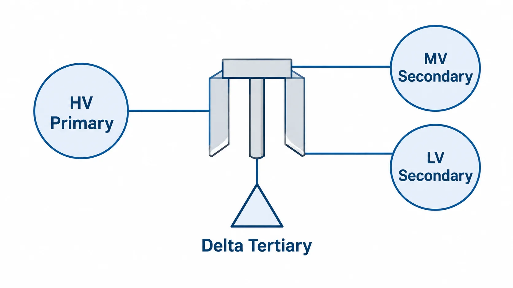
Across all these applications, the third winding performs one of four electrical duties. Classifying the duty is the most important step in specifying a three-winding transformer, because the same physical winding can do very different jobs.
| Üçüncü derece görev |
Electrical function |
Load on terminals? |
| Loaded output |
Transfers real power to a second bus at a third voltage |
Yes — continuous, near its rating |
| Stabilising (buried) delta |
Gives zero-sequence and triplen harmonic currents a closed path inside the tank |
No — terminals often not brought out |
| Auxiliary supply |
Feeds station service loads: cooling, chargers, lighting |
Yes — modest but continuous |
| Compensation / grounding |
Connects capacitors or reactors, or limits ground fault current |
Reactive or intermittent |
The stabilising role is the least visible and most misunderstood. When the main windings are wye-connected with a weak neutral path, unbalanced loads drive zero-sequence currents that have nowhere to go: the neutral shifts, phase-to-neutral voltages become unpredictable, and third-harmonic distortion appears on the output. A closed delta on the third winding fixes this — the zero-sequence components circulate harmlessly around the delta. That is a different job from deliberately earthing a secondary neutral, covered in our secondary grounding guide.
How to Size the Third Winding
Sizing rules differ sharply between loaded and buried tertiaries, and using the wrong rule is a common specification error:
- Buried stabilising delta: the industry convention is one-third of the main winding rating — the widely used 33.3% figure. During a ground fault on a wye winding, the ampere-turns in the delta reach roughly one-third of the faulted winding’s, so the copper must withstand those forces. Depending on zero-sequence duty, some specifications allow 25–50%.
- Single-phase load on one secondary phase: if one phase of the largest secondary can carry its full rating while the other two carry nothing — real in furnace and traction duty — the tertiary must balance it continuously. The 33.3% rule exists largely for this case, and treating it as continuous thermal duty, not a momentary rating, is what separates a correct specification from a marginal one.
- Auxiliary or loaded tertiary: size to the connected load with diversity and future expansion applied. When the tertiary is the station’s main supply, ratings near the full main winding are normal.
- Harmonic duty: modern core steels need well under 1% of rating for magnetising harmonics, so harmonics alone no longer justify a large delta — dedicated harmonic-mitigating designs handle that better.
Whatever the duty, insist on three impedance values between each winding pair on a stated common base — fault behaviour and cross-secondary voltage interaction follow from those numbers. Our percent impedance guide explains how to apply them.
One Three-Winding Transformer or Two Two-Winding Units?
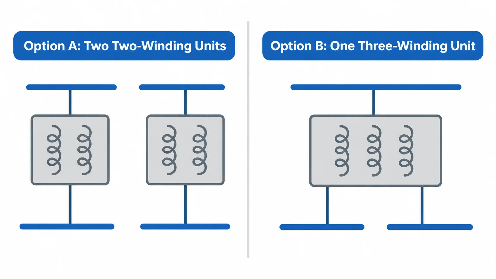
A three-winding unit typically adds roughly 15–25% to first cost over an equivalent two-winding design, so the comparison deserves to be deliberate.
| Kriter |
One three-winding unit |
Two two-winding units |
| First cost |
Lower for equal capacity — one tank, one HV bay |
Higher — two tanks, two connections |
| Space and civil works |
One foundation, one cooling system |
Two of everything |
| No-load losses |
One energised core |
Two energised cores |
| Arıza etkisi |
Both voltage systems down together |
Each system fails independently |
| Protection complexity |
Three-winding differential, tertiary overcurrent, three impedances |
Two standard schemes |
| Replacement flexibility |
Custom unit, long lead time |
Standard units, easier to substitute |
The pattern: choose the three-winding unit when both loads sit at the same site, the profile is stable, and space or HV bays are the binding constraint. Choose two two-winding units when loads are separated, redundancy matters more than space, or spares standardisation has real value. A three-winding unit concentrates both systems’ availability into one asset — that concentration is the feature being purchased, and it must be a conscious choice.
Specification and Protection Traps
Three-winding installations fail inspection for predictable reasons:
- The buried tertiary has no CTs. A stabilising delta circulates current internally with nothing measurable at any terminal, so differential protection cannot see faults confined to it. Specify gas and thermal protection for that region explicitly.
- Never operate a stabilising delta open. Removing the delta removes the zero-sequence path — neutral displacement and triplen distortion return. If a supplier offers a wye-wye unit without a stabilising winding, the grounding design must supply the path another way, typically a zigzag grounding transformer or neutral grounding resistor.
- Unloaded does not mean unrated. A buried winding still carries circulating fault and harmonic currents; its thermal and short-circuit withstand must be stated even though it never delivers a watt.
- Three impedances, not one. A single impedance figure hides the coupling that governs how a load step on one secondary disturbs the other.
- Auxiliary tertiaries need their own regime of voltage regulation, overcurrent coordination, and transfer schemes.
What If You Only Need Low Power?
Everything above describes three-phase power transformers from hundreds of kVA upward. Below about 10 kVA, purpose-built three-winding units are rare — the market solves the multi-voltage problem differently: dual-output windings, tapped secondaries, or two small transformers.
That is how our DT series step-up/step-down transformers work at the 100 VA–10 kVA scale: one enclosure provides both 110 V and 220 V output groups from a single wound assembly — the same “one source, several voltages” convenience at small scale, without the cost and protection complexity. If your application sits between these worlds, send us the load list and we will match the winding configuration; reach the team through our iletişim sayfası.
Sonuç
Three-winding transformers earn their place wherever one site needs two output systems plus a stabilising function from a single asset: hub substations, generator stations, mixed-voltage plants, and traction supplies. The discipline lies in classifying the third winding’s duty before specifying — loaded output, buried delta, auxiliary supply, or grounding path — then sizing it by the right rule and protecting it according to what the relays can actually see. Run the one-versus-two comparison deliberately; at low power, dual-output transformers often deliver the same convenience without the complexity.
Sık Sorulan Sorular
Üç sargılı transformatör ne için kullanılır?
Its dominant uses: substations supplying two distribution voltages from one transmission connection, generator step-up stations needing an auxiliary supply, industrial plants with mixed voltage systems, and wye-wye interconnections where a delta stabilising winding must circulate zero-sequence and harmonic currents to keep the neutral stable.
How large is the tertiary winding compared with the main windings?
A buried stabilising delta follows the one-third convention — about 33.3% of the main rating, sized to withstand ground-fault ampere-turns. Loaded auxiliary tertiaries are sized to their actual service load and can reach the full main rating.
What happens if the delta tertiary is left open?
The zero-sequence path disappears. Under unbalanced loading the neutral shifts, phase-to-neutral voltages become unpredictable, and triplen distortion appears on the output. A stabilising delta should never run open; use a zigzag grounding transformer or neutral grounding resistor if the path must come from elsewhere.
Can a three-winding transformer feed two loads at the same time?
Yes — that is its core purpose. The primary rating equals the combined power deliverable through both secondaries at once, hence nameplates like 60/40/20 MVA. Loading one secondary affects the other’s voltage through the impedance between the two secondary windings.
When should I use two two-winding transformers instead?
When the loads are physically separated, when redundancy matters more than space, when spares standardisation is valuable, or when protection simplicity is a priority. One three-winding unit is cheaper and more compact, but its failure takes both voltage systems down at once.
Do small transformers under 10 kVA ever have a third winding?
Rarely as a true three-winding design. At low power the need is met with dual-output or tapped secondary windings — converters providing both 110 V and 220 V from one enclosure — which achieve the same result with far less cost and complexity.