What is a Transformer
Transformer Fundamentals
Transformer are essential devices in the electrical world, using electromagnetic induction to transfer energy between circuits. Their main function is to adjust AC voltage levels—either increasing or decreasing them—while keeping the current’s frequency constant. This energy transfer happens without any direct conductive connection between the circuits, thanks to Faraday’s Law of Induction. This principle explains how a magnetic field can induce electromotive force (EMF) in an electric circuit.
Electric transformers play a crucial role in transferring power from one circuit to another without changing the frequency. They modify voltage levels, which inversely affects the electric current. The operation of transformers is rooted in electromagnetic and mutual induction principles.
History of Transformer
The transformers was invented in 1884 in England, marking a significant milestone in AC power utilization. It was first used at the Rome-Cerchi steam-powered power station in 1886, allowing for high-voltage generation and transmission (1,400 to 2,000 volts), which could then be reduced to safer levels for residential and commercial use.
Although the fundamental design remains unchanged, modern serve diverse applications. Large transformers in power plants facilitate high voltage transmission, minimizing power loss due to heat. Signal and audio transformers, for example, match microphone output to amplifier input.Measurement convert mainline power to lower voltages for safe measurement, while pulse transformers transmit digital signals in electronic devices.
How it works
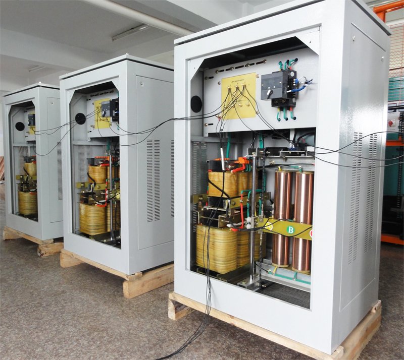
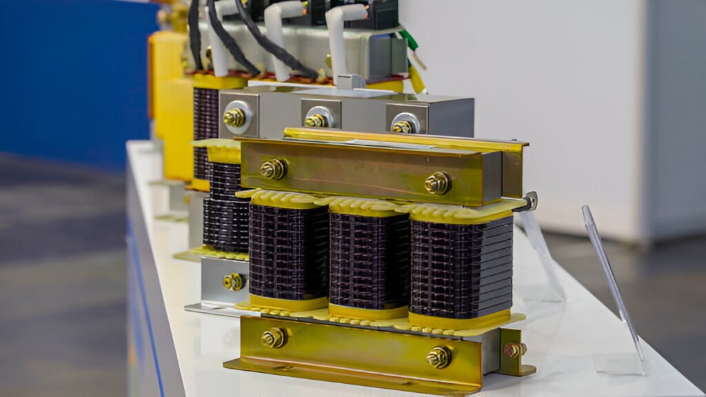
A basic transformers consists of three components: the magnetic core, primary winding, and secondary winding. The primary winding connects to an AC power source, generating an alternating magnetic field that induces EMF in the secondary winding. When this secondary circuit is closed, AC current flows through it. Both windings share a magnetic core made of laminated steel sheets, providing a low reluctance path for the magnetic field. The voltage ratio between output and input corresponds to the turn ratio of the windings: fewer turns in the secondary winding result in a step-down, while more turns create a step-up.
Transformers adhere to the law of energy conservation—energy cannot vanish but only change form. They do not generate electricity but adjust its intensity through electromagnetic induction. By coiling wires with varying loops around a core, voltage can be increased or decreased between circuits.

Three-Phase Transformer
While single-phase transformers have one primary and one secondary winding, three-phase feature three sets of windings. These are essential for powering industrial loads and generating three-phase power.
Key Points:
- Utilize electromagnetic induction for AC current transfer while modifying voltage.
- Comprise primary winding, secondary winding, and magnetic core.
- Range from large power station transformers to small electronic ones.
Components
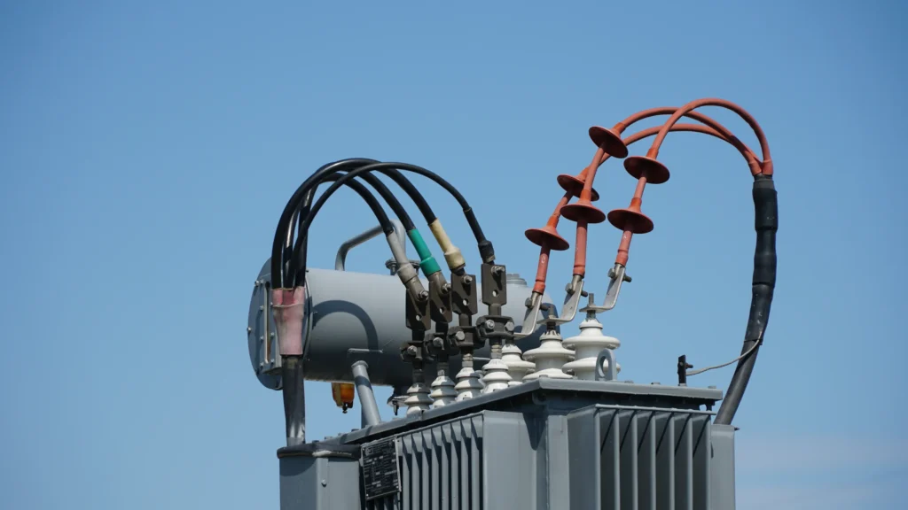
- Bushings: Insulated parts allowing electricity passage through transformer walls without direct contact.
- Core & Coils: Central components where induction occurs; coils manage voltage transformation.
- Load Break Switches: Enable manual disconnection from the grid for maintenance.
- Fuses: Protect against electrical faults by interrupting current flow during overloads.
- Voltage Adjustment Taps: Modify primary-to-secondary winding ratios to maintain correct voltage levels.
- Fluid: Acts as a coolant and insulator within liquid-filled transformers.
- Gauges: Monitor operational parameters like oil level and temperature.
Functions and Failures
Transformers transfer electrical energy between circuits via electromagnetic induction, primarily stepping voltages up or down for efficient long-distance transmission and appropriate application voltages.Failure may occur due to overload, power surge, short circuit, aging of components, improper maintenance, manufacturing defects or environmental influences. Overloading leads to overheating; surges can damage components; short circuits increase damaging current flow; aging degrades materials; poor maintenance exacerbates wear; defects may cause premature failure.

Common types
- Iron Core: High efficiency due to rapid magnetization/demagnetization; often use silicon steel plates.
- Isolation: Transfer power while isolating devices from the source; used in UPS systems and robotics.
- Ferrite Core: Minimize energy loss at high frequencies; customizable configurations.
- Step-Up: Convert lower voltages to higher ones with reduced amperage; used in power transformation.
- High Voltage: Handle 600-5000 volts for metering/protection in industrial contexts.
- Toroidal Core: Donut-shaped cores minimize leakage; lighter but costlier due to manufacturing complexity.
Benefits & Drawbacks of Electric Transformers
Benefits:
- Cost-effective voltage transmission/isolation.
- Versatile configurations (step-up/step-down).
- Multiple taps handle different input voltages.
Drawbacks:
- Require cooling to prevent insulation wear.
- Not suitable for direct current handling.
- Maintenance challenges include oil leaks and harmonics.
Common application scenarios
Transformers are crucial in adjusting AC circuit voltages/currents across industries:
Power Transmission & Distribution:
- Step-Up: Increase voltage for long-distance transmission with reduced losses.
- Step-Down: Lower voltage near communities for local distribution.
- Distribution: Further decrease voltage for household/business use.
Appliances & Electronics:
- Found in adapters converting high AC to low DC voltage.
- Safety isolation prevents high-voltage exposure.
- Impedance matching ensures audio equipment compatibility.
Other Applications:
- Industrial machinery regulation.
- Electric trains converting AC to DC power.
- Renewable energy systems converting DC from solar/wind sources to usable AC power.


