What Is an Autotransformer? Definition Types and Use
Published: Author: Lisa
An autotransformer is a type of electrical transformer that uses a single continuous winding to transfer electrical energy between circuits. Unlike a conventional transformer with separate primary and secondary coils, the autotransformer shares part of the same winding for both input and output. This design makes it more compact, lighter, and more efficient for applications where electrical isolation between circuits is not required.
Whether you encounter one in a power transmission substation, a motor starter panel, or a laboratory variable AC supply, the autotransformer is one of the most practical and widely used transformer types in electrical engineering. This guide explains how it works, what types exist, how it compares to conventional transformers, and where it fits in real-world systems.
What Is an Autotransformer?
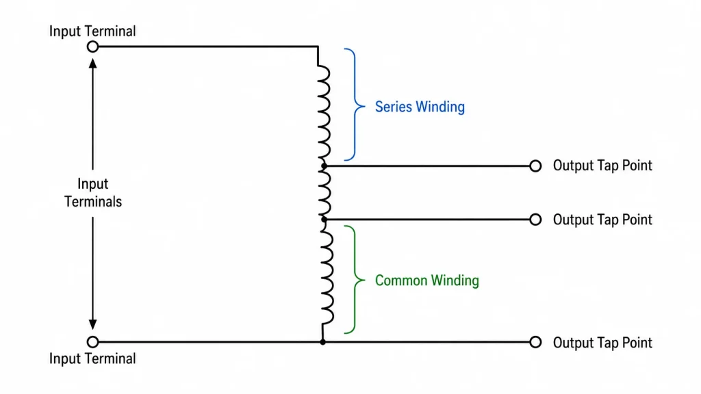
An autotransformer is a transformer with a single winding wound around a laminated magnetic core. The term “auto” comes from the Greek word for “self” — the single winding acts upon itself rather than relying on two separate coils. The winding has at least three terminals: two end terminals and one or more tap points along the coil.
The key distinction is that the primary and secondary circuits share part of the same conductive path. Power transfer occurs through both electromagnetic induction (across the core) and direct electrical conduction (through the shared winding section). This dual mechanism is what gives the autotransformer its efficiency and size advantages.
Because there is no galvanic isolation between input and output, an autotransformer is not suitable for every application. But where isolation is unnecessary — and the voltage ratio is within a practical range — it outperforms a conventional two-winding transformer of equivalent rating on cost, size, and efficiency.
How Does an Autotransformer Work?
The working principle of an autotransformer follows the same electromagnetic laws as any transformer: an alternating current in the winding creates a varying magnetic flux in the core, which induces a voltage across the winding proportional to the number of turns.
What makes the autotransformer different is how the input and output connections are arranged across that single winding. By selecting different tap points, the same physical device can step voltage up, step it down, or provide a variable output.
The Single-Winding Principle
Imagine a single coil with 200 turns connected to a 240 V AC supply. The full winding carries the input current and produces a magnetic field. If you connect a load across only 100 turns of that same winding, the induced voltage across that section will be 120 V — half the input.
The portion of the winding that carries both the input and output current is called the common winding. The remaining portion, which carries only the primary or secondary current, is the series winding. In a step-down configuration, the series winding sits between the input terminal and the tap point. In a step-up configuration, the series winding extends from the tap point to the far end of the coil.
Step-Up vs Step-Down Configuration
An autotransformer can function as a step-up or step-down device depending entirely on where the input voltage is applied and where the output is taken.
Feature
Step-Up Autotransformer
Step-Down Autotransformer
Input connection
Across a portion of the winding
Across the full winding
Output connection
Across the full winding
Across a portion of the winding
Output vs input
Vout > Vin
Vout < Vin
Turns ratio
Nout / Nin > 1
Nout / Nin < 1
Typical use
Boosting voltage for transmission
Reducing voltage for distribution or equipment
The voltage ratio follows the same turns-ratio formula used for all transformers: Vout / Vin = Nout / Nin. The difference is that both Vin and Vout share part of the same physical conductor.
Types of Autotransformers
Autotransformers come in several configurations, each optimized for a different class of application. Understanding the types helps you match the right unit to the job.
Fixed-Ratio Autotransformers
A fixed-ratio autotransformer has permanently set tap points that produce a specific output voltage for a given input. These are the most common type found in voltage conversion equipment. For example, a unit with a 2:1 ratio converts 240 V input to 120 V output with no user adjustment needed.
Fixed-ratio units are widely used in industrial machinery, appliance voltage conversion, and distribution transformers where the input-to-output relationship is stable. They are simple, robust, and require no moving parts. For projects requiring compact step-up or step-down conversion within a 3:1 ratio, a fixed-ratio autotransformer is often the most cost-effective choice.
Variable Autotransformers (Variac)
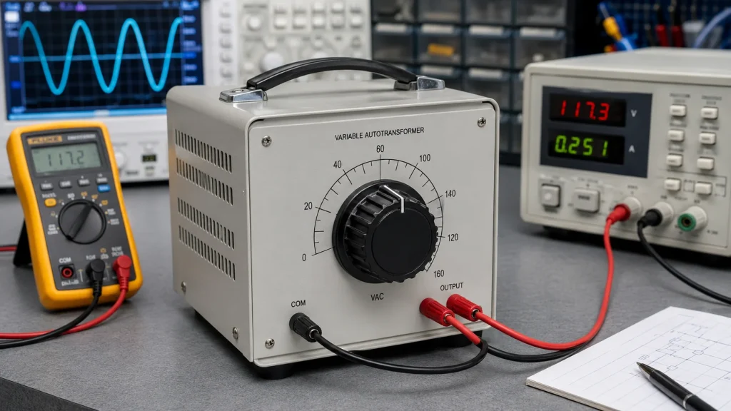
A variable autotransformer replaces fixed tap points with a sliding carbon brush that moves along the winding, providing continuously adjustable output voltage from zero to slightly above the input voltage. The most well-known brand name for this design is Variac, though many manufacturers produce them under different trade names.
Variable autotransformers are essential in testing laboratories, R&D facilities, repair shops, and educational settings where equipment must be tested across a range of input voltages. They are also used for light dimming, heater control, and motor speed adjustment in applications where waveform distortion from electronic controllers is unacceptable.
Three-Phase Autotransformers
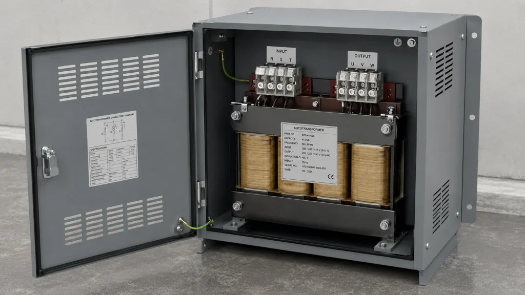
For industrial power systems operating on three-phase AC, autotransformers can be built in three-phase configurations. These typically use three single-phase autotransformer units connected in a star (wye) or delta arrangement, or a single three-limb core with shared windings.
Three-phase autotransformers are common in motor starting, power distribution, and interconnection between transmission networks operating at different voltage levels — for example, linking a 132 kV system to a 66 kV network. Their compact size and high efficiency make them attractive for high-power applications where the voltage ratio is modest.
Autotransformer vs Conventional Transformer
Choosing between an autotransformer and a conventional dual-winding transformer depends on your application’s requirements for isolation, voltage ratio, fault tolerance, and budget. The table below compares them across the criteria that matter most.
Criterion
Autotransformer
Conventional Transformer
Winding arrangement
Single continuous winding
Two separate primary and secondary windings
Electrical isolation
None — input and output electrically connected
Galvanic isolation between circuits
Size and weight
Smaller and lighter
Larger and heavier for equivalent rating
Cost
Lower material and manufacturing cost
Higher cost
Efficiency
Higher — typically 98% or above
Lower for the same power rating
Practical voltage ratio
Best up to approximately 3:1
Any ratio
Short-circuit current
Higher — lower impedance
Lower — higher impedance limits fault current
Safety
Less safe — winding failure can expose output to full input voltage
The widespread use of autotransformers in power systems and industrial equipment is driven by several clear advantages:
Compact size and lower weight. Because only one winding carries the power, the autotransformer requires less copper and a smaller magnetic core. A unit can be up to 50% smaller than an equivalent dual-winding transformer when the voltage ratio is around 2:1.
Higher efficiency. Reduced copper losses (less winding material) and lower core losses (smaller core) yield operating efficiencies of 98% or higher in power-grade units. Less energy wasted as heat also means reduced cooling requirements.
Lower cost. Less copper, less core steel, and simpler manufacturing translate directly into a lower unit price. For B2B buyers and OEM projects, this cost advantage scales with quantity.
Better voltage regulation. The lower leakage reactance of a single-winding design means the output voltage stays closer to the rated value as the load changes, which is valuable in distribution and motor starting applications.
Higher power capacity per unit size. For the same physical footprint, an autotransformer can handle a larger kVA rating than a conventional transformer.
Smooth output adjustment. Variable autotransformers deliver clean, continuously adjustable AC voltage without the waveform distortion introduced by electronic dimmers or thyristor controllers.
Disadvantages and Limitations
The autotransformer design also has important limitations that dictate where it should not be used:
No electrical isolation. The input and output share a direct conductive path. Any fault, surge, or voltage transient on one side appears on the other. This is the single most important reason autotransformers are not used in safety-critical isolation applications such as medical equipment or consumer power supplies.
Winding failure risk. If the common section of the winding opens or breaks, the full input voltage can appear at the output terminals under light-load conditions. This creates a serious safety hazard and potential equipment damage.
Limited voltage ratio. The cost and size advantage diminishes as the ratio between input and output voltage increases. Beyond approximately 3:1, a conventional transformer becomes the more practical choice.
Higher fault currents. The lower internal impedance means short-circuit currents can be significantly higher than in a dual-winding transformer. Protection devices must be sized accordingly.
Not for DC. Like all transformers relying on electromagnetic induction, autotransformers cannot step up or step down DC voltage.
Common neutral constraints. In star-connected three-phase autotransformers, the neutral point is shared. You cannot independently ground or isolate the primary and secondary neutrals.
Common Applications of Autotransformers
Autotransformers appear across the entire voltage spectrum, from consumer electronics to high-voltage transmission grids.
Application Area
Typical Use
Transformer Type
Power transmission
Interconnecting grids at different voltages (e.g., 220 kV to 132 kV)
Fixed-ratio, three-phase
Distribution regulation
Tap-changing autotransformers compensate for line voltage drop
Fixed-ratio with tap changer
Motor starting
Reduced-voltage starting of large induction motors (50%, 65%, 80% taps)
Fixed-ratio
Voltage conversion
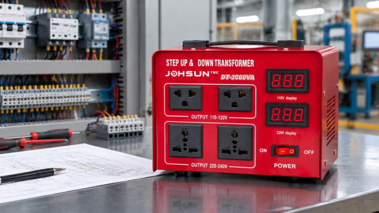
Running 110 V equipment on 220 V mains, and vice versa
Fixed-ratio, single-phase
Laboratory testing
Variable AC supply for equipment testing and calibration
Variable (Variac)
Railway electrification
Extending feeder distances on 25 kV AC traction networks
Fixed-ratio
Audio systems
Impedance matching between amplifier output and speaker loads
Fixed-ratio
For industrial buyers and distributors, step-up and step-down autotransformers in the STU and DT series cover most voltage conversion, motor starting, and equipment power-matching requirements with CE and IC certification.
An autotransformer is a practical, efficient, and cost-effective solution for voltage conversion, motor starting, power system interconnection, and laboratory testing — in any scenario where electrical isolation is not a requirement. Its single-winding design delivers higher efficiency in a smaller footprint compared to a conventional dual-winding transformer of the same rating. For help selecting the right autotransformer for your application, read our selection guide or contact our engineering team to discuss your requirements.
FAQ
What is the difference between an autotransformer and a normal transformer?
An autotransformer uses a single winding shared between input and output, while a normal (conventional) transformer has two electrically separate windings — a primary and a secondary. The autotransformer is smaller, cheaper, and more efficient but does not provide electrical isolation. A conventional transformer provides galvanic isolation between circuits, making it safer for applications where output must be electrically separated from input.
Does an autotransformer provide isolation?
No. An autotransformer does not provide galvanic isolation. The input and output circuits are electrically connected through the shared winding. For applications requiring isolation — such as medical devices, safety circuits, or consumer power supplies — a conventional dual-winding transformer or an isolation transformer must be used instead.
Can an autotransformer be used for both step-up and step-down?
Yes. The same autotransformer can operate in either mode depending on how the input and output connections are arranged. Many commercially available units are designed and labeled for both directions. However, always check the manufacturer’s specifications, as some units are optimized for a specific direction.
What is the maximum voltage ratio for an autotransformer?
Practically, autotransformers are most cost-effective at voltage ratios up to about 3:1. Beyond this range, the material savings diminish and the lack of electrical isolation becomes harder to justify. For very high step-up or step-down ratios, a conventional two-winding transformer is the standard choice.
Why are autotransformers more efficient than conventional transformers?
Autotransformers achieve higher efficiency because they use less copper (lower I2R losses) and a smaller magnetic core (lower hysteresis and eddy-current losses) than an equivalent-rated dual-winding transformer. Additionally, part of the power is transferred by direct electrical conduction rather than magnetic coupling alone, which further reduces losses.
What is a Variac?
A Variac is a brand name for a variable autotransformer that provides continuously adjustable AC output voltage. It uses a rotating knob connected to a sliding carbon brush that moves along the exposed winding surface, allowing the user to dial in any voltage from zero to slightly above line voltage. Variacs are widely used in laboratories, repair shops, and production testing environments.
Can an autotransformer convert DC voltage?
No. Autotransformers, like all transformers, operate on the principle of electromagnetic induction, which requires a changing magnetic field produced by alternating current. DC voltage does not create the varying flux needed for induction. To convert DC voltages, you need a DC-DC converter or an inverter-rectifier combination.
A control transformer steps a 380 V or 480 V supply down to the 120 V or 24 V that relays, contactor coils and PLC inputs run on. Learn how it works, why inrush VA — not sealed VA — sets the rating, and how to size, tap, fuse and ground one.
A practical guide to transformer live and neutral wiring: how to identify L and N terminals, connect them correctly, and avoid the hidden shock hazards of a reversed input.