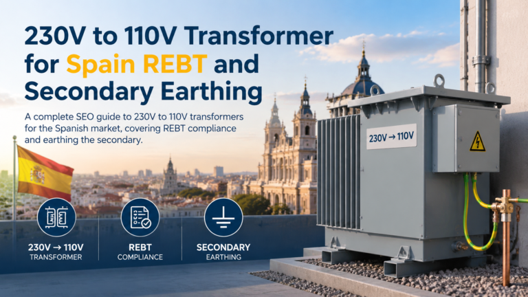
230V to 110V Transformer for Spain: REBT and Secondary Earthing
230V to 110V transformer for Spain: REBT compliance, ITC-BT-18 and ITC-BT-24, earthing the secondary and UNE-EN IEC 61558 documentation.
Read More
 English
When selecting a transformer for industrial, commercial, or laboratory use, two common types often enter the conversation: the autotransformer (available in both step-up and step-down configurations) and the control transformer. While both devices change voltage levels for AC circuits, they differ fundamentally in construction, operating principle, electrical isolation, cost, and suitable applications. Understanding these differences helps you avoid misapplication that could damage equipment, create safety hazards, or waste budget on unnecessary features.
Johsun Tech is a specialized manufacturer of industrial transformers, serving engineers, OEMs, and system integrators worldwide. Our product portfolio spans step-up and step-down autotransformers, control transformers, and custom magnetic components — each engineered for reliability in demanding industrial environments. With a deep focus on transformer technology and a commitment to application-driven design, we bridge the gap between technical specification and real-world performance. This article draws on our in-house engineering expertise to help you make an informed selection between two commonly misunderstood transformer types.
An autotransformer is a transformer that uses a single continuous winding wound around a laminated core to serve as both the primary and secondary winding. Unlike a conventional two-winding transformer where the primary and secondary are electrically separate, an autotransformer has a shared winding where portions of the coil function for both input and output. The winding has at least three terminals: two fixed end terminals and one or more intermediate tap points.
Voltage transformation in an autotransformer follows the same turns-ratio principle as a standard transformer — the output voltage is proportional to the ratio of turns between the tap point and the common terminal. Because part of the energy is transferred directly through electrical conduction (rather than purely by magnetic induction), autotransformers achieve higher efficiency and require less copper and core material for the same power rating.
The same autotransformer can operate in either step-up or step-down mode depending on how the input and output connections are arranged:
In a step-down configuration, the input voltage is applied across the full winding (the fixed end terminals), and the load is connected between one fixed terminal and a tap point closer to the common terminal. The number of turns between the tap and common terminal is less than the total winding turns, so the output voltage is proportionally lower than the input. The turns ratio k = N2 / N1 is less than 1.
In a step-up configuration, the connections are reversed: the input is applied across a portion of the winding via a tap point, while the output is taken from the full winding across the fixed end terminals. This causes the output voltage to exceed the input voltage because the number of turns on the output side is greater than on the input side. The turns ratio k becomes greater than 1.
Multi-tap autotransformers allow users to select among several preset output voltages by connecting the load to different tap points along the winding, making them highly flexible for applications requiring variable or adjustable voltage.

A control transformer is a two-winding isolation transformer specifically designed to supply stable voltage to control circuits, motor starters, relays, contactors, timers, and other industrial control components. Unlike an autotransformer, a control transformer has electrically separate primary and secondary windings that are coupled only through the magnetic core. This provides full galvanic isolation between the input supply and the control circuit.
Control transformers are built to handle the unique demands of industrial control circuits, which often include high inrush currents when contactors and relays energize. They are typically designed with a high-quality silicon steel core and generous regulation characteristics to maintain stable secondary voltage even during momentary overloads. Most control transformers also incorporate fuse protection on both the primary and secondary sides.
The fundamental distinction lies in the winding configuration and the resulting electrical isolation, but the differences extend across cost, size, safety, and application suitability.
| Feature | Autotransformer | Control Transformer |
|---|---|---|
| Winding Type | Single continuous winding shared by primary and secondary | Two separate windings with magnetic coupling only |
| Electrical Isolation | No isolation between input and output; they share a common electrical path | Full galvanic isolation between primary and secondary |
| Size and Weight | Smaller and lighter for equivalent power rating | Larger and heavier for the same power rating |
| Copper Usage | Less copper required; significant material savings, especially near unity turns ratio | Full copper for both primary and secondary windings |
| Efficiency | Higher due to combined conduction and induction energy transfer | Lower relative to autotransformer of equivalent rating |
| Cost | Lower material cost; more economical, especially for ratios near 1:1 | Higher material and manufacturing cost |
| Voltage Regulation | Better regulation under load due to lower impedance | Good regulation, specifically designed for inrush handling |
| Safety | No isolation; a winding failure can expose the load to full primary voltage | Safer for control circuits; isolation protects operators and sensitive components |
| Harmonics & Noise | Does not block harmonic transfer between primary and secondary | Provides some degree of harmonic and noise attenuation |
| Short-Circuit Current | Lower impedance means higher potential fault currents | Higher impedance limits short-circuit current to safer levels |
| Common Voltage Ratios | Flexible; any ratio achievable via tap selection | Typically 480:120, 240:120, 480:24, or similar standard control voltages |
Not Sure Which Transformer Fits Your Application? Talk to Our Engineers. Voltage ratio, surge loads, isolation requirements — our team can help you cut through the specs and get the right transformer for your panel, machine, or lab setup. Reach out for a free technical consultation and competitive quote. Request a Quote
An autotransformer uses a single coil wound on a laminated silicon steel core. The coil has multiple tap points physically brought out to terminals. For a given VA rating, the core can be smaller because less magnetic material is needed — only the portion of power transferred inductively requires core flux, while the remainder is conducted directly. The winding wire gauge varies along the coil: the common section carrying the difference current can use heavier gauge wire, while sections carrying lower current can use finer wire.
A control transformer has two physically separate coils wound on a common laminated core, typically using high-grade grain-oriented silicon steel to minimize losses. The primary winding is usually wound closest to the core, with the secondary wound over it, separated by insulation layers or a bobbin. The core is often larger than an equivalent autotransformer because all energy must transfer inductively through the magnetic circuit. Many control transformers are built with an epoxy or vacuum-impregnated varnish finish to resist moisture, dust, and vibration common in industrial environments.

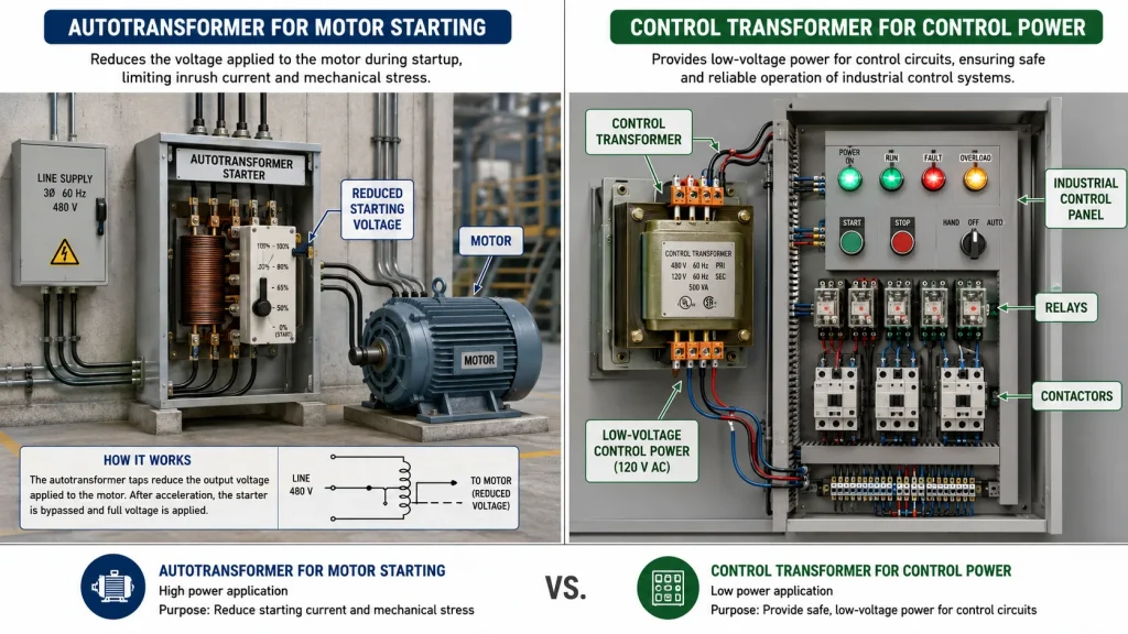
The single most important decision factor between an autotransformer and a control transformer is electrical isolation. In an autotransformer, the primary and secondary share a common conductor. If a fault occurs in the common winding — such as an open circuit or insulation breakdown — the full supply voltage can appear at the load terminals. This can destroy downstream equipment and pose a serious electric shock hazard to personnel.
A control transformer, by contrast, keeps the primary and secondary circuits galvanically isolated. Even if the primary winding fails, the fault voltage does not directly transfer to the secondary. The secondary can also be grounded independently according to local electrical codes (e.g., NEC Article 250), creating a safer control circuit for operators and maintenance technicians.
For any application where people directly interact with controls, or where low-voltage electronics are powered from a high-voltage supply, a control transformer is the standard choice. Autotransformers are better suited for fully enclosed, unattended equipment where isolation is not required and efficiency or cost savings are the priority.
Use the following decision criteria to select the right transformer type:
| Application Scenario | Recommended Transformer | Reason |
|---|---|---|
| Motor starter control panel (480V to 120V) | Control Transformer | Isolation required for operator safety; inrush handling for contactors |
| Operating 230V equipment on a 115V supply | Autotransformer (Step-Up) | Efficient, compact voltage conversion; isolation not required for enclosed equipment |
| PLC and HMI power supply | Control Transformer | Protects sensitive electronics from line-side transients and noise |
| Variable voltage testing in a lab | Variable Autotransformer (Variac) | Continuous voltage adjustment needed; compact and efficient |
| Distribution line voltage regulation | Autotransformer | High power, near-unity ratio, automatic tap changing for line compensation |
| CNC machine control circuit | Control Transformer | Galvanic isolation protects CNC controller; stable voltage under varying machine loads |
Autotransformers and control transformers serve distinctly different roles in electrical engineering. An autotransformer — available in step-up and step-down configurations — excels when you need compact, efficient, and cost-effective voltage conversion where electrical isolation is not required. A control transformer is the right choice whenever safety isolation, noise rejection, inrush handling, or code compliance is necessary, particularly in industrial control circuits.
The decision ultimately comes down to one question: Does your application require galvanic isolation between the supply and the load? If the answer is yes, choose a control transformer. If not, consider whether the cost, size, and efficiency benefits of an autotransformer serve your needs — and always verify that your installation complies with applicable electrical codes and safety standards.
This comparison is one of many technical resources we publish to support smarter component selection. Whether you’re specifying transformers for a control panel, troubleshooting voltage conversion in a retrofit project, or sourcing custom magnetics for a new product line — you’ll find detailed product guides, application notes, and datasheets to keep your project moving. Visit our homepage to explore our complete transformer catalog and the latest engineering content.
Technically, yes — an autotransformer can step voltage down for a control circuit. However, it is generally not recommended and often prohibited by electrical codes because it lacks galvanic isolation. Without isolation, a fault on the primary side can expose control devices and operators to line voltage. Most safety standards require an isolated control transformer for control circuits in industrial equipment.
A control transformer requires two separate windings, more copper, a larger core, and additional manufacturing steps including insulation between windings and built-in fusing. An autotransformer achieves the same VA rating with less material because part of the power is transferred by direct electrical conduction rather than magnetic induction.
If the common section of the winding (shared by both primary and secondary) opens, the transformer can no longer step voltage down. Under light-load conditions, the transformer may act as an inductor in series with the load, potentially applying close to full input voltage at the output. This is a critical safety concern and a primary reason autotransformers are avoided in safety-sensitive circuits.
Yes, this is a common and appropriate application. Step-up autotransformers are widely used for voltage conversion of motors, heating elements, and other enclosed equipment. Ensure the transformer has adequate VA rating for the motor’s starting current, and always provide proper overcurrent protection on both the input and output sides.
Control transformers are designed primarily for step-down operation, typically from higher line voltages (480V, 240V) down to control-level voltages (120V, 24V). While a two-winding transformer can technically be used in reverse (step-up), this is not recommended for control transformers because they are optimized with the specific primary and secondary impedances matched to their intended direction of power flow.
Autotransformers typically achieve 96% to 99% efficiency depending on size and ratio, while two-winding control transformers of similar rating typically achieve 90% to 95% efficiency. The gap widens when the voltage ratio is close to unity, where autotransformer copper savings are greatest and losses are lowest.