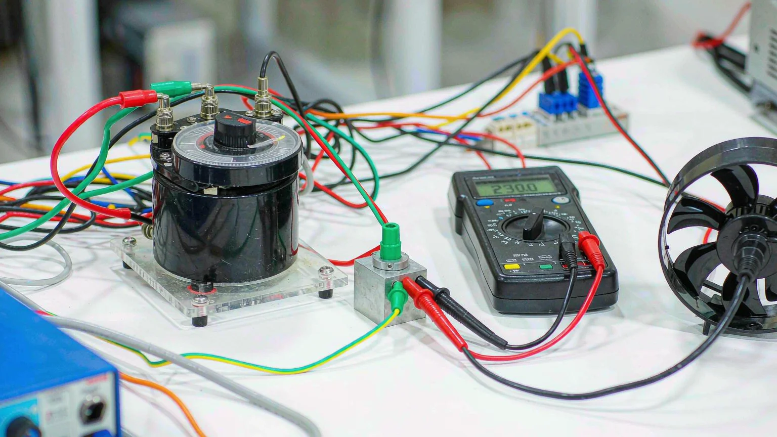
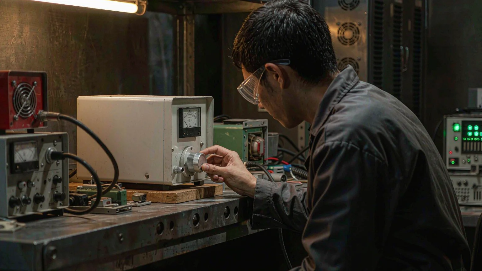
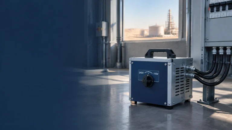
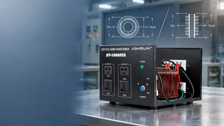
A variable transformer — almost always called a variac on the test bench — is an autotransformer with a sliding carbon brush on a exposed toroidal winding. Turning the knob moves the brush along the turns, so the output voltage sweeps continuously from 0 V up to roughly the input voltage (some models reach 110–120% of nominal). There are no fixed taps to select and no contactor switching: the output follows your hand smoothly, with very little waveform distortion, which is exactly what variac testing needs.
That simplicity is also its main limitation. Because a variac is an autotransformer, its output is not galvanically isolated from the mains: the secondary shares the primary winding, so a “low” output voltage can still reference live potential. For safe bench work, pair the variac with an isolation transformer downstream, or at minimum power the rig through a properly earthed outlet with RCD protection. Keep that caveat in mind through every procedure below.
For buyers, the practical takeaway is that a variac is a test instrument wearing a transformer’s clothes: a controllable AC source for variable transformer applications such as low-voltage bring-up, voltage-limit checks, soft-starting motors and running burn-in tests — not just another box that converts 220 V to 110 V.
Common Variable Transformer Applications
Most requests we see from small manufacturers and labs fall into five buckets. Each application maps to a specific thing the variac does, at a typical operating point:
Application
What the variac does
Typical operating point
Low-voltage bring-up (new or repaired units)
Ramps voltage from near zero so faults appear at low energy instead of at full mains
Start ~10–25% of rated, step up in stages
Voltage-limit and sag testing
Holds the load at deliberately low or high line conditions
-15% to +10% of nominal, held per spec
Motor soft-start and characterization
Raises voltage gradually so inrush and torque can be observed
Ramp from 0 V over several seconds
Heater and lamp power control
Adjusts RMS voltage to trim temperature or brightness
Continuous duty, resistive load
Burn-in / aging runs
Applies staged or elevated voltage for hours to screen early failures
Staged profile, see burn-in section
If your only need is a fixed 110 V↔220 V conversion for daily operation, you do not need the knob at all — a fixed step-up/step-down unit is cheaper and more robust. The step-up and step-down transformer category covers those; the rest of this article is about the adjustable case.
Sizing a Variac for the Test Bench
Undersizing is the most common procurement mistake. A variac’s rating is stated in kVA at its maximum output voltage; at low dial settings the available output current does not increase to compensate. Size by load current, not wattage:
Switch-mode power supplies: check the input current at the lowest line voltage you will test at — input current rises as input voltage falls for constant-power loads.
Motors and transformers: multiply running current by 3–5× for starting inrush, or ramp slowly so magnetizing current stays manageable.
Worked example: a 1.5 kW heater on 220 V draws 6.8 A, so a 2 kVA variac (≈9 A) is comfortable. The same bench running a 500 W universal motor should assume 4–6 A inrush — still fine at 2 kVA, but only because you ramp rather than slam full voltage. Our TDGC2J variable transformer series (0.5–5 kVA) is sized on exactly this basis, with a voltmeter on the dial so the operator never guesses the output.
One more sizing subtlety: the headroom above 100% output comes from the same winding carrying more current per turn. If your burn-in test plan holds 110% for long stretches, size the unit so that condition sits at 80% of its nameplate kVA.
Safe Bench Setup, Step by Step
A five-minute setup routine prevents most variac accidents:
Check the dial position first. Always power up with the output at zero. If the previous operator left it at maximum, your device-under-test sees full mains instantly.
Fuse or breaker the input according to the variac rating, and confirm earth continuity to the test rig.
Add isolation when probing. If you will clip an oscilloscope or any earthed instrument onto the circuit, feed the load through an isolation transformer — probing a direct autotransformer output can short the reference through the scope’s earth.
Connect the load and set meters: one voltmeter on the variac output, one clamp meter on the load current.
Ramp, don’t switch. Bring the output up while watching current; if it climbs disproportionately at low voltage, stop.
That last checkpoint catches more faults than any other single test: a healthy unit draws a modest, roughly proportional magnetizing current as you ramp, while a shorted turn, failed MOV or blown rectifier shows up as a current spike well before full voltage is applied.
Voltage Testing Procedures
Low-voltage bring-up
For a unit fresh off the repair bench or a first-article sample, use a staged ramp: 10% of rated voltage and hold two minutes, then 25%, 50%, 75%, and finally 100%, watching no-load current at each stage. Because the core is energized gradually, you also avoid the saturation inrush that a hard connection to mains would cause — the same physics we covered in the transformer core saturation guide. A unit that passes each stage with proportionate current and normal temperature is very unlikely to fail destructively at full power.
Voltage-limit checks
Many specs require proof that a device works across a line window, commonly 198–242 V on a 220 V system. Set the variac to each limit, let the load reach thermal steady state, then record operation, current and any protective trips. For power supplies this doubles as a regulation check; for transformers under test it pairs naturally with the workflow in our turns ratio test guide, where the variac supplies a safe, adjustable excitation voltage.
When the device under test is a motor, the ramp procedure doubles as a soft-start. Voltage, torque and current rise together from zero, and you can find the minimum voltage at which the motor reaches speed — useful data for sizing reduced-voltage starters, a topic expanded in our motor load sizing guide.
Running a Burn-In Test with a Variac
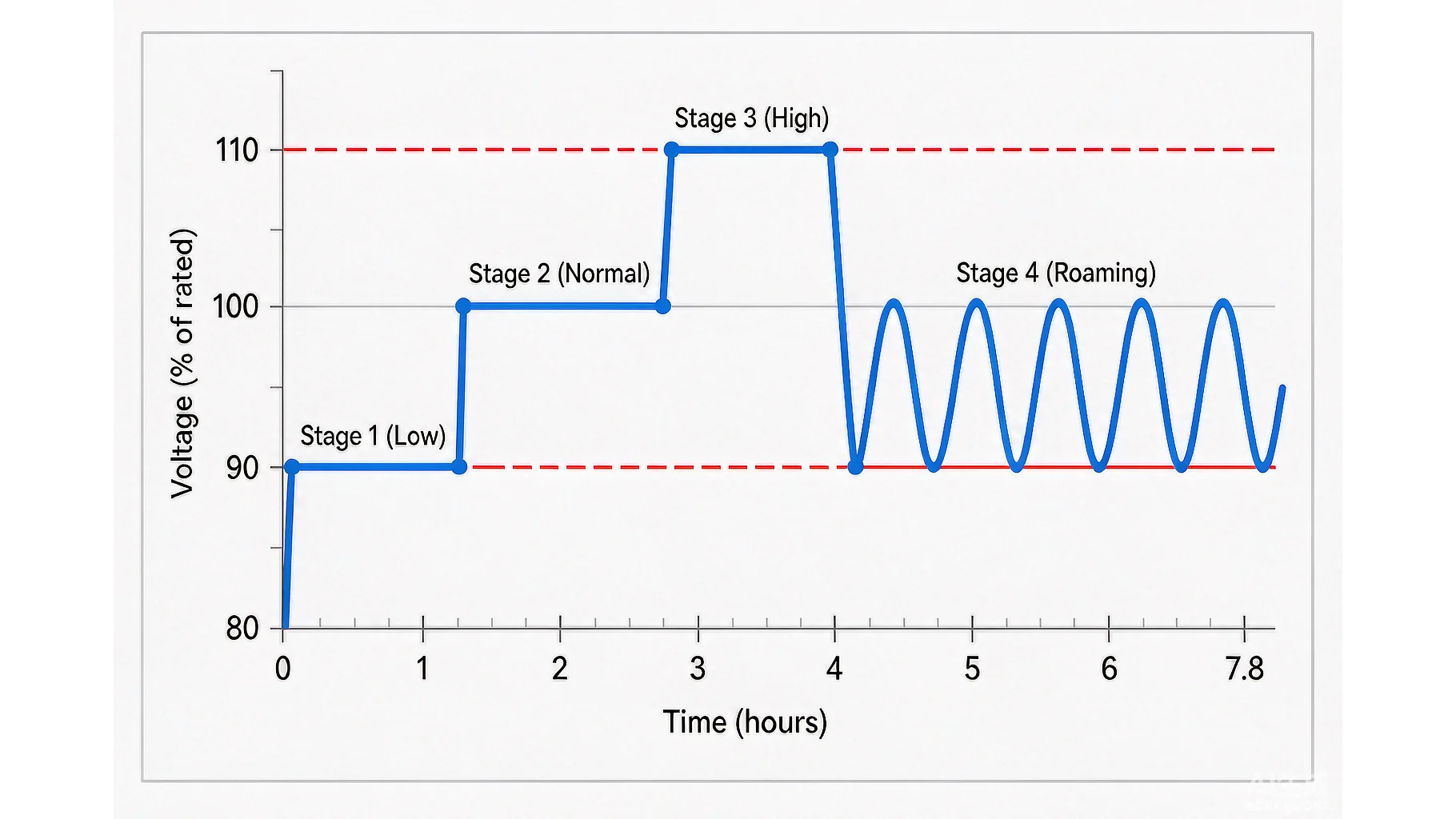
A burn-in test (also called power-on aging) runs finished units under power for hours so that infant-mortality failures — weak capacitors, cold joints, marginal insulation — fail in the plant rather than at the customer. The variac is what makes the voltage profile possible: industry aging lines typically move through low, normal, high and roaming stages without ever switching the unit off.
A practical profile for small electrical products looks like this:
Stage
Voltage setting
Duration
What it screens for
1 — Low
~90% of rated
0.5–1 h
Start-up stability, undervoltage behavior
2 — Normal
100% rated
2–4 h
Thermal drift, intermittent joints
3 — High
110% of rated
1–2 h
Overvoltage stress, marginal insulation
4 — Roaming
Cycle 90% ↔ 110%
1 h
Sensitivity to mains fluctuation
During the run, log output voltage, load current and case temperature at fixed intervals. A rising current at constant voltage is the classic precursor of an internal fault; a temperature that never plateaus means the design or the profile needs review. After the profile completes, run a full functional check at room temperature before release. Units that fail are documented with the time and stage of failure — that data often shows which component lot or process step to audit.
Two cautions keep the burn-in honest. First, confirm every unit’s rated tolerance before applying the 110% stage — the stress level is meant to be uncomfortable, not destructive. Second, keep power continuous; units that cool down between stages have not really been aged.
When a Fixed Transformer Is the Better Choice
If the goal is simply to run 110 V equipment from a 220 V supply all day, a variac spends its precision on a problem you don’t have — and its brush contact becomes a maintenance item instead of a feature. Fixed step-up/step-down units such as the STU series (100 VA–2 kVA) are the right tool for permanent voltage conversion, with multiple output sockets and no operator adjustment to get wrong. Reserve the variac for the bench, where the adjustment is the product.
Common Mistakes to Avoid
Powering up at mid-dial. Zero the output before every connection.
Sizing by watts alone. Motor inrush and switch-mode input current at low line both exceed the naive number.
Probing without isolation. An earthed scope ground on an autotransformer output can create a dead short.
Using a variac as a stabilizer. It holds the voltage you set, not the voltage the load needs; for automatic correction you need a voltage regulator.
Long holds above 105%. Brush and winding heating accumulate; continuous overvoltage is a rating question, not a knob position.
Conclusion
A variac earns its place on the bench by turning mains into a controllable test variable: staged bring-up, limit checks, soft-starts and multi-hour burn-in tests all become routine instead of risky. Size it by load current with inrush margin, keep the isolation caveat in view, and follow a written ramp and aging profile so results repeat across operators. If you are equipping a lab or an aging line and need help matching a unit to your loads, browse the transformer range or reach out with your test spec for a sizing recommendation.
FAQ
What is the difference between a variac and a normal transformer?
A variac is an autotransformer with a sliding brush, so its output voltage is continuously adjustable from 0 V to around the input voltage. A normal transformer has a fixed turns ratio and one or more fixed output voltages.
Can a variac step up the voltage?
Most single-phase variacs reach about 110–120% of the input voltage at the top of the dial, which covers overvoltage testing. For large permanent step-up ratios, use a fixed step-up transformer instead.
Is variac output safe to touch for testing?
No. Because a variac is not isolated from the mains, low output voltage can still reference live potential. Use an isolation transformer for probe-connected work and keep RCD protection in the circuit.
What voltage should a burn-in test use?
A common profile is 90% → 100% → 110% of rated voltage in timed stages, sometimes with a roaming cycle between 90% and 110%. The exact values should follow the product’s rated tolerance and your reliability spec.
How do I choose the kVA rating for a variac?
Size by load current at the lowest test voltage, add margin for motor inrush or switch-mode input characteristics, and keep long 110% holds at around 80% of the nameplate kVA.
Not sure of the capacity? Send the input and output voltage, the country standard and the load list to sales@johsuntech.com and we will confirm the model within one working day.
A transformer cannot create cycles the supply does not have. What actually changes inside a 60Hz machine on 50Hz power, which loads genuinely do not care, and the three ways to convert frequency properly.
Gulf sites run 230/240V at 50Hz; imported US and Japanese equipment expects 110/120V at 60Hz. Sizing, wiring, ambient derating and the frequency limits of a step-down transformer, written for contractors and procurement teams.
Autotransformer advantages depend on the voltage ratio. This guide quantifies where they hold, shows the 2:1 crossover, and lists five situations where an autotransformer should not be used.