Transformer Core Saturation: Causes, Effects and How to Avoid It
Published: Author: Lisa
Transformer core saturation is the point where the steel core can no longer absorb more magnetic flux, so extra voltage stops producing proportional flux and starts producing a runaway magnetizing current instead. On dry-type transformers from 100 VA to 10 kVA it is rarely a manufacturing defect; it is almost always an operating mismatch — wrong frequency, a supply running high, a half-wave load, or a winding connected the wrong way. This guide covers the five common causes, how to recognise saturation before it damages the winding, and how to prevent it. For product context, see our low-voltage transformers range.
What Transformer Core Saturation Actually Means
A core is a magnetic circuit, and magnetic materials respond linearly only up to a limit. Plot flux density (B) against magnetizing force (H) and you get the B-H curve: a steep linear region, a rounded knee, then a flat saturation region where more current produces almost no more flux. Grain-oriented silicon steel saturates near 2.0 T; good 50/60 Hz designs run at 1.4 T to 1.6 T. Past the knee — typically 1.7 T to 1.8 T — permeability collapses and the primary behaves like an air-cored coil. Core geometry is covered in transformer construction and iron core structure.
Bmax = Vrms / (4.44 × f × N × Ac)
Here V is applied voltage, f frequency, N primary turns and Ac effective core area. Raise the numerator or lower the denominator and the core moves toward saturation.
Five Causes of Core Saturation
1. Volts per hertz above the design value
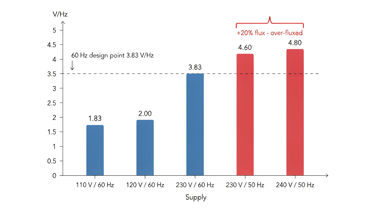
The most common cause. A transformer is designed for a ratio of voltage to frequency, not for a voltage alone. A 230 V, 60 Hz unit runs at 3.83 V/Hz; feed it 230 V at 50 Hz and you demand 4.60 V/Hz, a 20% rise in flux. A core designed at 1.45 T now sits at 1.74 T — past the knee.
2. Supply overvoltage and the wrong primary tap
Flux density is proportional to applied voltage, so a supply running 8% high pushes flux 8% higher. Margins are thinner than people assume: a unit designed at 1.55 T is near the knee at 1.75 T, so about 13% overvoltage is enough. Long feeders and poorly regulated generators are classic candidates, and so is the wrong primary tap.
3. DC offset from half-wave and phase-controlled loads
Symmetrical current gives symmetrical flux. Add a DC component and the flux waveform shifts up or down the B-H curve, clipping on one half-cycle long before it would reach the knee symmetrically. Half-wave rectifiers and unbalanced phase control do this. A few percent of DC can consume most of the headroom.
4. Residual magnetism and switching at the wrong instant
After switch-off or a cleared fault the core can retain remanent flux. Energize at an instant that adds to it and first-cycle flux can approach twice the steady-state peak, driving the core deep into saturation for several cycles. Frequent contactor switching makes it worse.
5. Connection and winding errors
Using a secondary as a primary is a frequent error when a step-up unit is repurposed as a step-down. Turns correct for the low-voltage side are far too few for the high-voltage side, so flux rises by the turns ratio. Reversed polarity on a split primary does the same to part of the core.
What a Saturated Core Looks and Sounds Like
Saturation leaves evidence, and most of it appears at no load — the opposite of what people expect, because magnetizing current is a no-load phenomenon.
Symptom
What it indicates
Loud, harsh hum with a buzzing edge, present at no load
Flux density above the knee; laminations driven hard. Normal magnetostriction hum is smoother
Core and winding hot within minutes at no load
Core loss rising steeply; the core is doing work it was never sized for
Primary current far above expected magnetizing current
Permeability collapse; current no longer limited by inductance
Peaky, flat-topped current waveform on a scope
Classic saturation signature — narrow pulses at the flux peaks
Breaker trips on energization but holds afterwards
Asymmetric inrush from residual flux, not a short circuit
Secondary voltage slightly high and distorted
Harmonic-rich magnetizing current coupling through
Odd harmonics (3rd, 5th) on the supply
Saturated core injecting distortion into the installation
The thermal path matters most. A saturated core turns excess magnetizing current into heat in the laminations, directly against the winding insulation, and the mechanisms match causes and hazards of transformer overheating — but arrive faster.
Hum is easy to confuse with loose laminations or a resonant enclosure; why low-voltage transformers make noise separates normal 100/120 Hz hum from a core in saturation.
Saturation vs Inrush Current
These get conflated, and the distinction changes what you do about it. Inrush current is a transient: a few cycles to a couple of seconds after energization, caused by the flux offset at the switching instant, decaying as the core settles. Saturation is a state: the core is beyond its flux limit for as long as the over-V/Hz condition persists. Trip at switch-on and then run cool — inrush. Hum and heat continuously — saturation. Motor starting is separate; see sizing a step-up transformer for motor loads.
Working Out Your Flux Margin
You do not need core dimensions for a first judgement. Compare applied volts per hertz with nameplate volts per hertz; if applied is higher, the core is being pushed harder than it was designed for.
Supply
Volts per hertz
Notes
110 V / 60 Hz
1.83
North American small equipment
120 V / 60 Hz
2.00
Common 60 Hz design point
220 V / 60 Hz
3.67
Some export markets
230 V / 60 Hz
3.83
Common 60 Hz design point
230 V / 50 Hz
4.60
20% more flux than 230 V / 60 Hz
240 V / 50 Hz
4.80
Worst case for a 60 Hz unit
400 V / 50 Hz
8.00
Three-phase 50 Hz
480 V / 60 Hz
8.00
Three-phase 60 Hz
A 230 V, 60 Hz unit with 298 primary turns and a 20 cm² core runs at B = 230 / (4.44 × 60 × 298 × 0.002) = 1.45 T. On 230 V, 50 Hz the same unit sits at 1.74 T — past the knee. Holding 1.45 T at 50 Hz allows only about 192 V, or 83% of nameplate: the familiar 50/60 derating factor, which turns a 1500 VA unit into 1250 VA. The DT-1500VA step-up and step-down transformer is a typical example of the size class where this must be settled before installation rather than after.
How to Test for Transformer Core Saturation
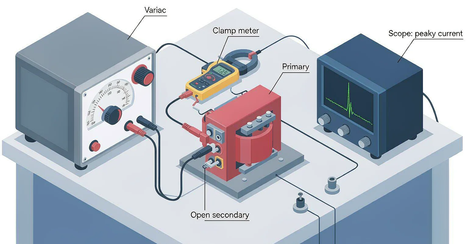
The no-load current test is the most useful check and needs little equipment: a variable transformer, a true-RMS ammeter and ideally a scope with a current probe.
Disconnect all secondary loads; saturation is a primary-side condition and shows up cleanest with the secondary open.
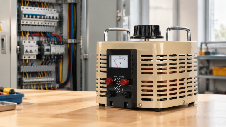
Feed the primary from a variable transformer, starting at zero.
Raise voltage in 10% steps and record primary current at each step.
Plot current against voltage. A healthy core rises slowly and turns upward only near rated voltage.
If the curve turns sharply upward at 80% to 90% of rated voltage, the margin is gone.
Small dry-type units draw about 5% to 10% of rated current at no load; larger ones sit lower. The shape of the curve matters more than the single reading. Our article on transformer no-load losses explains how the same test separates core loss from excitation current. A saturated core also produces narrow high-amplitude current pulses, with a crest factor well above the 1.4 of a sine wave.
How to Avoid Core Saturation
Match frequency, not just voltage. Treat a 60 Hz transformer on 50 Hz as an 83% voltage device, or order a unit wound for the actual supply frequency.
Check the real supply, not the nominal one. Measure at the terminals at peak load. A feeder at 245 V on a 230 V nameplate has already spent 6.5% of the margin.
Keep DC off the primary. Put half-wave and phase-controlled loads on the secondary, and derate if they must sit on the primary side.
Reduce switching stress. Use zero-crossing switching or a soft start, and allow a settling period before full load.
Demagnetize after a fault. Bring the primary up slowly from zero with a variable transformer to walk the core back down the B-H loop and clear remanence.
Verify the winding configuration. Confirm series or parallel grouping, tap selection and polarity before energizing.
Specify flux density, not just kVA. State maximum supply voltage, frequency, tolerance and load type in the RFQ, then ask for the design peak flux density at worst-case V/Hz. A supplier who can quote that number is designing the core; one who cannot is guessing.
Conclusion
Core saturation is a flux budget problem, and the budget is set by volts per hertz. Keep applied V/Hz at or below the nameplate value, keep DC out of the primary, respect residual magnetism when switching, and verify the winding configuration before energizing. If the unit saturates with all of those inside limits, the core was undersized and only a custom winding adds headroom. If you are specifying for a supply that is not the standard 230 V or 400 V at 50 Hz, the step-up and step-down transformer range covers 100 VA to 10 kVA with windings for non-standard frequencies — send us your supply details and we will confirm the flux margin before you order.
FAQ
What is transformer core saturation in simple terms?
The core has a maximum amount of flux it can carry. Once that limit is reached, more voltage no longer adds proportional flux and the primary current rises sharply instead. The transformer heats and hums without doing extra useful work.
Can a saturated transformer recover?
Yes, if the insulation is undamaged. Remove the cause and demagnetize the core by raising primary voltage slowly from zero with a variable transformer. If it has run hot for a long time, insulation damage is permanent and the winding should be tested first.
Does saturation happen at no load?
Yes, and that is where it is easiest to see. Magnetizing current is a no-load condition, so a saturated transformer heats and buzzes with nothing connected to the secondary.
Why does a 60 Hz transformer saturate on a 50 Hz supply?
Flux density is inversely proportional to frequency. Dropping from 60 Hz to 50 Hz at the same voltage raises flux by 60/50, or 20%. A core designed at 1.45 T moves to 1.74 T, past the knee for silicon steel. Operate it at about 83% of nameplate voltage, or fit a 50 Hz winding.
How do I tell saturation from overload?
Disconnect the load. A saturated transformer still heats and hums with the secondary open, and its primary current stays high. An overloaded transformer cools and its current falls to the magnetizing value as soon as the load is removed.
How a buck-boost transformer works: series-winding polarity, differential kVA sizing with single-phase and three-phase examples, and the five limits that decide when it is the wrong tool.
How to size a step-up transformer for a motor: locked-rotor current, kVA code letters, starting kVA by method, voltage-dip and thermal-duty checks, plus the traps most guides miss.
A practical dry-type vs oil-immersed transformer comparison for low-voltage buyers: cooling class, fire safety, overload, maintenance and installed cost, plus a ten-minute selection sequence.