Step-Up Transformer for Motor Loads: Inrush and kVA Sizing
A motor is the one load that punishes an undersized step-up transformer immediately. A heater draws what its nameplate says; a motor draws five to eight times its running current for the first second, and if the transformer cannot deliver that surge, secondary voltage collapses, torque falls with the square of the voltage, and the motor stalls. Step-up transformer sizing for motor loads therefore starts from starting kVA, not running kVA, and ends with a voltage-dip check that most guides skip.
This guide covers 100 VA to 10 kVA: small pumps, compressors, machine-tool motors, blowers, and exported machinery arriving with a 400 V motor on a 220 V site. For resistive or electronic loads, the general step-up transformer selection guide is a better starting point.
The Short Answer
Step-up transformer sizing has three gates: starting kVA, voltage dip, then thermal duty.
- Calculate running kVA from full-load current, efficiency and power factor.
- Multiply by the starting ratio of the method you will actually install.
- Pick a unit at least 1.25 times running kVA, large enough to hold the dip you can tolerate.
- Confirm it can absorb that starting kVA at your starts-per-hour.
A direct-on-line start typically lands at 2.5 to 4 times running kVA; a soft starter or VFD lands near 1.3 to 1.6 times. That gap is the cost of ordering the transformer before deciding the starting method.
Two Inrush Currents, Only One on the Nameplate
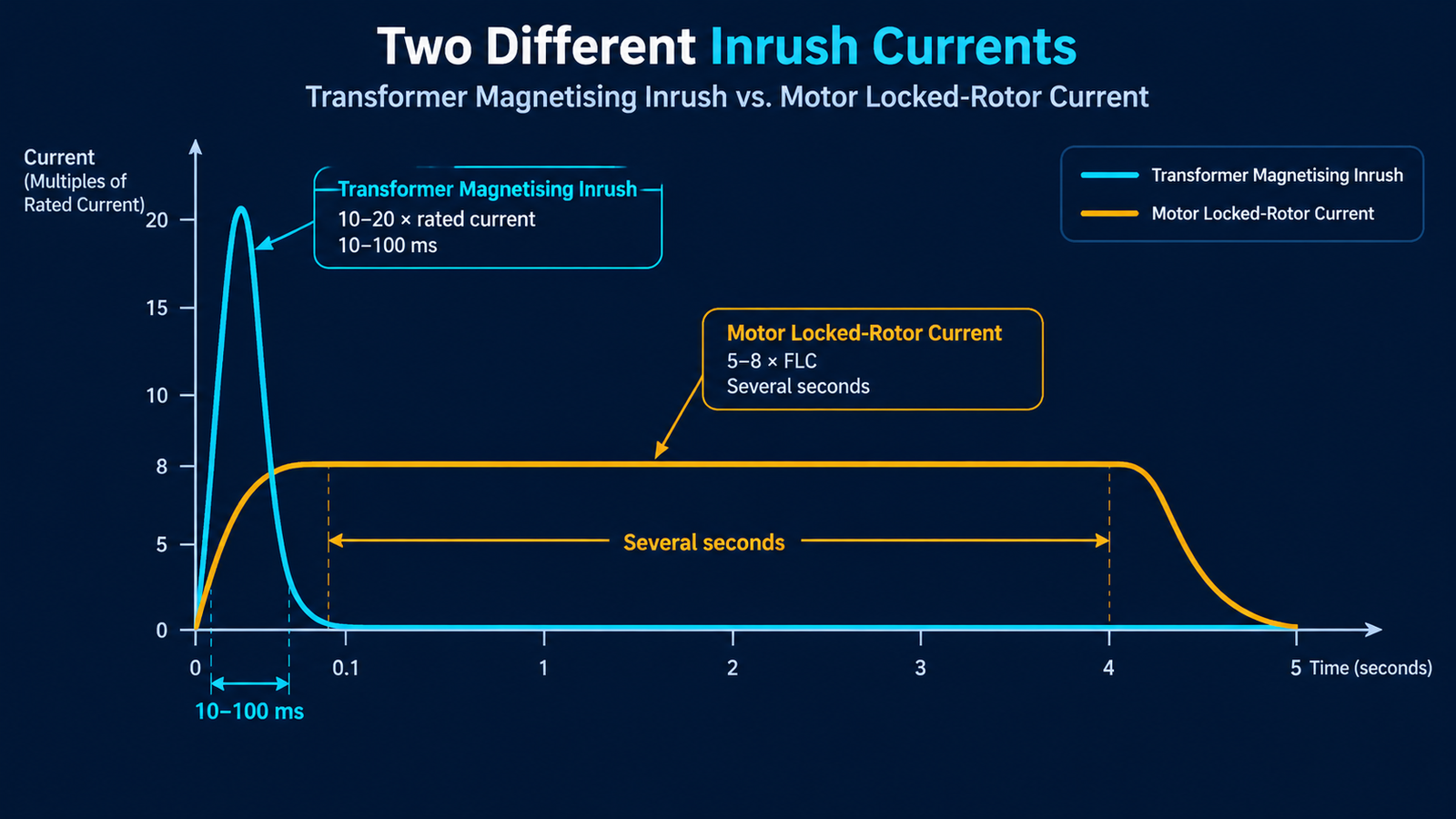
Most sizing mistakes here come from mixing up two unrelated currents that both get called “inrush.”
Transformer magnetising inrush happens when you energise the transformer itself. The core saturates for a few cycles and the primary draws a spike of ten to twenty times rated current for 10 to 100 milliseconds. It depends on where on the voltage wave the switch closes, so it is not repeatable and appears on no nameplate. It affects your upstream breaker, not your transformer rating.
Motor locked-rotor current is the current a stationary motor draws at full voltage. It lasts a fraction of a second to several seconds while the rotor accelerates, and it is fully predictable from the motor data. This is the number that decides transformer size. On a step-up unit feeding a motor, both events can land within the same second, because the contactor that starts the motor also energises the transformer: your breaker rides through both, your transformer carries only the second.
Step 1: Pull the Starting Data Off the Nameplate
Step-up transformer sizing starts with four nameplate numbers: rated voltage, frequency, full-load current (FLC), and one indicator of starting current. On North American motors that indicator is a kVA code letter; on IEC motors it is the locked-rotor current ratio from the datasheet, or design letter N or H under IEC 60034-12.
The code letter states locked-rotor kVA per horsepower. Lower letters mean gentle starting; K through V means a motor demanding three times the starting kVA of an A-code unit of the same size.
| Code letter |
Locked-rotor kVA per hp |
What it usually means |
| A – D |
0 – 4.5 |
Low-inrush designs, often larger frames |
| F – H |
5.0 – 7.1 |
Common general-purpose industrial motors |
| J – L |
7.1 – 10.0 |
Higher inrush, typical of older or low-cost designs |
| M – V |
10.0 and above |
Very high locked-rotor kVA; expect a much larger transformer |
With no code letter and no datasheet, assume 6 times FLC for a three-phase IEC motor and 4 times for a capacitor-start single-phase motor, and state that in your RFQ.
Step 2: Convert Starting Current Into Starting kVA
Running kVA comes first. Three-phase: kVA = √3 × VLL × IFLC ÷ 1000. Single-phase: kVA = V × IFLC ÷ 1000.
Starting kVA is running kVA multiplied by the locked-rotor current ratio: kVAstart = kVArun × (ILR ÷ IFLC).
Worked example: a 2.2 kW, 400 V three-phase motor, FLC 5.0 A, locked-rotor ratio 6.5. Running kVA = 1.732 × 400 × 5.0 ÷ 1000 = 3.46 kVA. Starting kVA = 3.46 × 6.5 = 22.5 kVA.
That is what the transformer must deliver for a couple of seconds on a direct-on-line start — six times the running demand. A 5 kVA unit runs this motor all day and still sags when the contactor closes. Motor loads need their own method, not the general transformer capacity calculation used for mixed loads.
Step 3: Match the Transformer to the Starting Method
Starting method changes the answer more than motor size does, and the transformer cannot be re-rated later.
| Starting method |
Starting current vs FLC |
Practical transformer size |
Notes |
| Direct on line |
5 – 8 × |
2.5 – 4 × running kVA |
Full starting torque; worst case for the transformer |
| Star-delta |
1.7 – 2.6 × |
1.6 – 2 × running kVA |
Torque drops to one third; needs six motor terminals |
| Soft starter |
2.5 – 4 × |
1.5 – 2 × running kVA |
Ramp time must respect the transformer’s limit |
| VFD |
1.1 – 1.5 × |
1.3 – 1.6 × running kVA |
Input current close to sinusoidal load current |
| Capacitor start, 1-phase |
3 – 6 × |
2 – 3 × running kVA |
High inrush on every start, often several per hour |
Do not use the “1 kVA per horsepower” rule of thumb. It was written for motors in the tens of kilowatts on utility-scale transformers; on a 0.75 kW motor it is meaningless.
Step 4: Check the Voltage Dip You Can Tolerate
A transformer is not a stiff source. Its impedance decides how far secondary voltage falls while the motor accelerates, and torque falls with the square of that voltage. A 20 percent dip leaves 64 percent of rated torque — often not enough for a loaded pump, so the motor sits at locked-rotor current until the overload trips.
For the transformer’s own contribution: dip (%) ≈ %Z × (starting kVA ÷ transformer kVA). Small dry-type transformers typically sit between 3 and 8 percent impedance, so take the figure from the datasheet.
| Voltage during start |
Available torque |
Practical consequence |
| 95 % |
90 % |
No issue; normal starting |
| 90 % |
81 % |
Acceptable for most centrifugal loads |
| 85 % |
72 % |
Marginal for loaded positive-displacement pumps and conveyors |
| 80 % |
64 % |
Risk of failure to accelerate; contactors may chatter |
| Below 75 % |
56 % |
Stall; overload protection operates on every start |
Keeping the dip under 10 percent is the usual working target. If the maths says you need a 20 kVA transformer to hold 10 percent on a 3.5 kVA motor, the transformer is the wrong tool — step-up transformer sizing has hit its limit and a VFD is the right answer.
Step 5: Check Starting Duty, Not Just the Peak
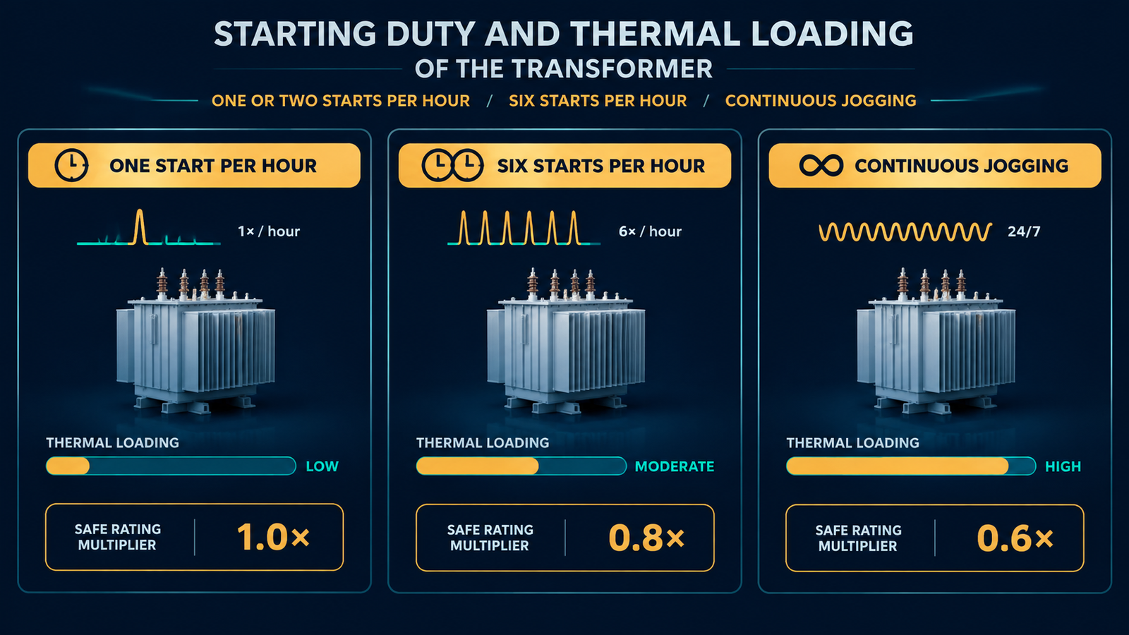
Starting kVA decides whether the motor accelerates; starting frequency decides whether the transformer survives. Each start dumps heat into the windings faster than convection removes it. One or two starts per hour are comfortable at 1.5 times running kVA; five to ten, or frequent reversing, need the upper end of the range and a checked temperature-rise class. A class F unit at class B rise has real margin here; a class B unit at its limit does not. The usual overload calculation assumes a steady load and understates what repeated starts do.
Traps That Only Appear on Step-Up Duty
Reverse-wired step-down units. A 400/230 V step-down unit can physically be fed from its 230 V winding, but that winding was designed as a secondary — insulation, taps and current rating all assume the other direction. Some units are genuinely reversible; many are not. Confirm in writing.
Light-load overvoltage. Small transformers have poor regulation by large-transformer standards. A unit with 5 percent regulation sits 5 percent above nominal at no load — 420 V on a 400 V secondary. Usually fine within a motor’s ±10 percent tolerance, but check it if your supply already runs high.
Overload protection placement. The motor’s overload relay must measure motor current, which lives on the secondary. On the primary it sees a lower current and will not protect the motor. Set the relay to FLC at the secondary voltage; the primary breaker covers the transformer and wiring only.
Frequency. A 60 Hz motor on a 50 Hz supply needs its voltage cut by 5/6 to hold V/Hz, or the core saturates and the motor overheats. A transformer boosting 230 V to 400 V for a 400 V, 60 Hz motor on a 50 Hz site does the opposite of what that motor needs.
A Bench Check Before You Commit to a Size
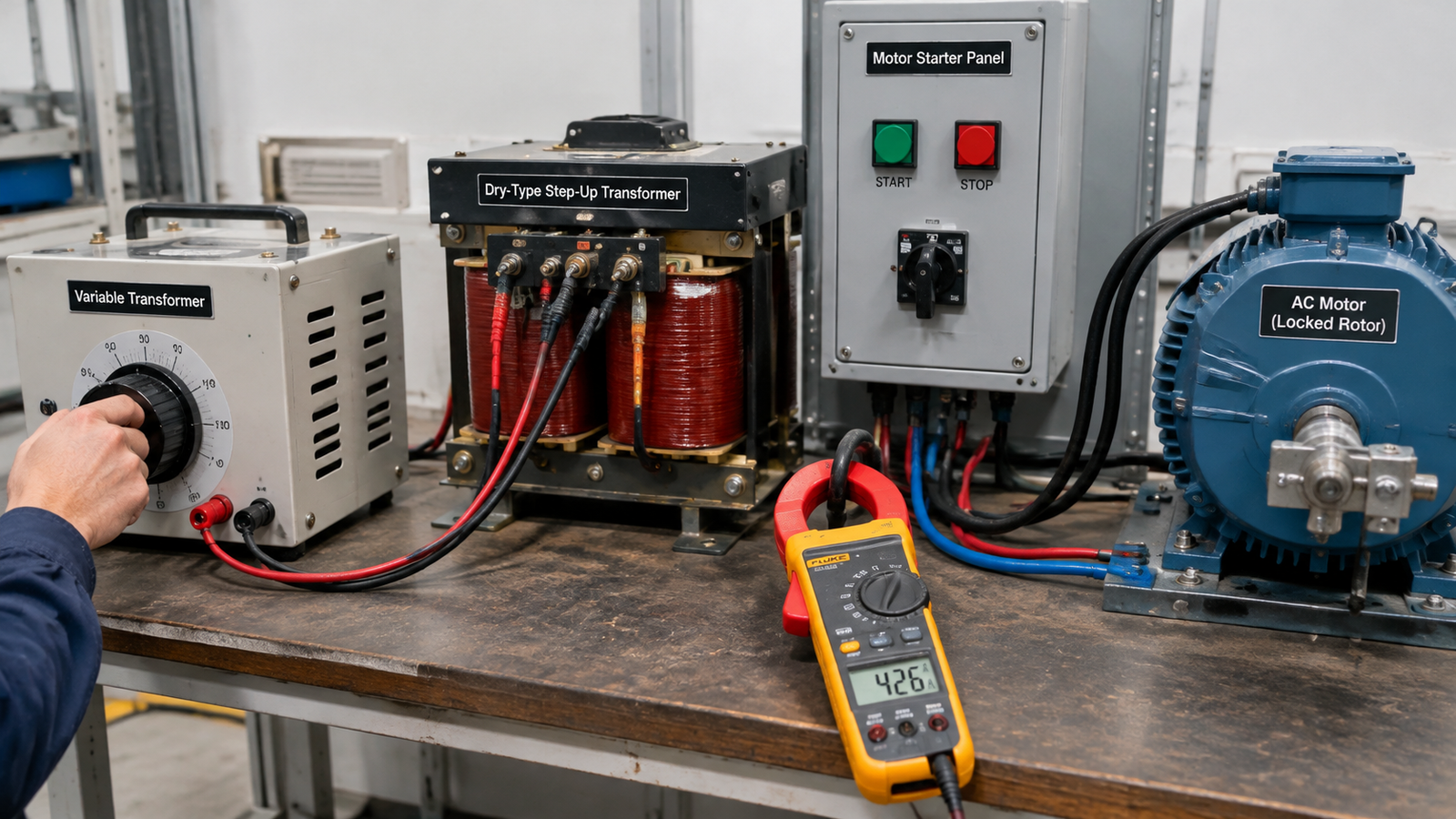
If the motor is on site and its data is uncertain, measure it. Feed it through a variable transformer with the rotor locked, raise the voltage slowly from zero, and record current at each step. Extrapolating to rated voltage gives the locked-rotor current of your motor, not a code letter’s assumption.
RFQ Checklist for a Motor-Load Step-Up Transformer
- Motor nameplate: kW or hp, voltage, frequency, FLC, kVA code or locked-rotor current.
- Site supply: voltage, phase, frequency, and whether it is stable or fluctuating.
- Starting method and starts per hour.
- Required transformer kVA and the calculated dip at that size.
- Impedance, temperature-rise class and reverse-wiring confirmation stated explicitly.
- Ambient and enclosure type — an enclosed unit in a hot panel needs derating.
Conclusion
Step-up transformer sizing for a motor is three calculations, not a rule of thumb: starting kVA from locked-rotor current, a voltage-dip check against the torque the load needs, and a thermal check against how often it starts. Get those right and a 5 kVA unit runs a 2.2 kW motor for years; get them wrong and a 10 kVA unit still trips on every start.
With the motor nameplate and the site voltage in hand, our step-up and step-down transformer range from 100 VA to 10 kVA covers most small motor applications, with custom ratios, taps and impedance values available on request.
Frequently Asked Questions
What size step-up transformer do I need for a 1.5 kW motor?
A 1.5 kW three-phase motor with a locked-rotor ratio of 6 needs about 2.0 kVA running and 12 kVA starting. On a direct-on-line start, plan on 5 kVA; with a VFD, 3 kVA is enough.
Can I run a motor from a transformer smaller than its starting kVA?
Yes, if the starting method limits current and the duty is light. A soft starter or VFD holds starting current near 2 to 3 times FLC, so a transformer just above running kVA carries the motor. On a direct-on-line start, undersizing stalls it.
Why does my step-up transformer trip the breaker when the motor starts?
The breaker usually sees transformer magnetising inrush and motor locked-rotor current at the same instant. A motor-rated breaker curve, a short delay, or energising the transformer before the motor start normally resolves it.
Can one transformer supply several motors?
Yes, sized for the worst case: the largest motor starting at locked-rotor current while all others run at full load. Sum every motor’s running kVA, subtract the largest motor’s running kVA, then add its starting kVA. Sequence the starts so two motors never accelerate together.