Funktionsweise und Verdrahtung eines dreiphasigen Autotransformators
Veröffentlicht: Autor: Lisa
A three phase auto transformer changes the voltage of a three-phase AC supply while keeping all three phases electrically connected through shared windings. Its main function is to step voltage up or down efficiently when galvanic isolation is not required. Because part of each winding is common to both input and output, the design can use less copper and core material than a comparable two-winding transformer, especially when the input and output voltages are relatively close.
Three-phase autotransformers are used for industrial voltage matching, motor starting, voltage correction, equipment testing, and power distribution. This guide explains their working principle, construction, symbol, wiring concept, benefits, limitations, and the information a buyer should provide before selecting a unit.
What Is the Function of a Three Phase Auto Transformer?
The primary function of a three-phase autotransformer is to convert one three-phase AC voltage level into another without changing the supply frequency. Depending on its winding taps and terminal arrangement, it can operate as either a step-up or step-down device.
Common functions include:
Voltage matching: adapting plant power to imported machinery or equipment designed for another nominal voltage.
Small-ratio voltage correction: converting among levels such as 380 V, 400 V, and 415 V.
Motorstart: temporarily reducing the voltage applied to a motor to limit starting current.
Distribution support: linking compatible three-phase systems where electrical isolation is not part of the design requirement.
Testing and commissioning: providing a specified three-phase voltage for compatible industrial loads.
A three-phase autotransformer does not create three-phase power from a single-phase source, and it does not change frequency. It also normally does not isolate the load from the supply. JOHSUN’s Startseite gives an overview of transformer and voltage-conversion product families for different applications.
Wie funktioniert ein dreiphasiger Autotransformator?
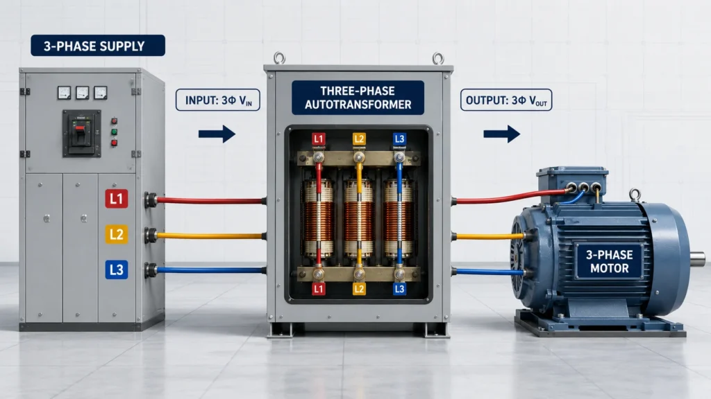
The operating principle is electromagnetic induction combined with a direct conductive connection through the shared winding. Each phase has a winding with one or more taps. The input is connected across one portion of the winding, while the load is connected across another portion.
A three-phase AC supply energizes the three phase windings.
The alternating current produces magnetic fluxes displaced by 120 electrical degrees.
The flux induces voltage along each winding according to the number of active turns.
The selected taps establish the input-to-output voltage ratio.
Power reaches the load partly by induction and partly through the common conductive winding section.
For an ideal winding, the voltage ratio follows the turns ratio. If the output uses fewer effective turns than the input, voltage is reduced. If it uses more turns, voltage is increased. In practical equipment, winding losses, temperature rise, regulation, load power factor, and allowable current must also be considered.
Wichtig: The input and output of an autotransformer are electrically connected. A lower output voltage must not be treated as touch-safe or isolated from the supply.
Construction of 3 Phase Auto Transformer Systems
Die construction of 3 phase auto transformer equipment generally follows one of two approaches: a bank of three single-phase autotransformers or one integrated three-phase unit. Both approaches provide one autotransformer winding function per phase.
Three-Unit Transformer Bank
Three single-phase units can be connected as a three-phase bank. This arrangement can simplify transport, servicing, and spare-unit replacement. It may also offer installation flexibility for high-capacity projects, although it typically needs more interconnections and floor space.
Integrated Three-Phase Unit
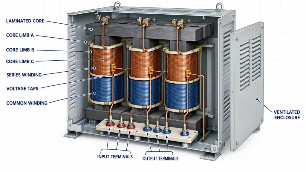
An integrated design places the three phase windings on a shared laminated magnetic core inside one enclosure. It can be more compact and economical, with fewer external connections. The core, winding conductors, insulation system, terminals, cooling path, enclosure, taps, protective devices, and temperature class are selected for the required kVA and duty.
Construction Element
Funktion
Buyer Check
Laminated magnetic core
Provides a controlled path for three-phase magnetic flux
Core type, noise, losses, and temperature rise
Shared windings
Serve as common and series sections for voltage conversion
Conductor material, insulation class, and current rating
Voltage taps
Set the input/output ratio or provide adjustment
Tap range, step size, and whether taps are off-circuit
Terminals
Connect supply, load, neutral if provided, and protective earth
Markings, phase sequence, lug size, and access protection
Cooling and enclosure
Controls temperature and protects internal parts
Indoor/outdoor use, IP rating, airflow, and ambient limits
How to Read a 3 Phase Auto Transformer Symbol
A 3 phase auto transformer symbol shows three autotransformer winding paths or a simplified three-phase representation. Unlike the symbol for an isolation transformer, the input and output connections are shown on the same winding rather than on two separated coils.
On drawings, look for these details:
Three phase conductors, commonly identified as L1, L2, and L3 or A, B, and C.
Input and output taps drawn on the same phase windings.
A star or wye point when the design includes a common neutral.
Delta or wye connection notation where applicable.
Voltage ratios, kVA rating, frequency, tap positions, and terminal identifiers.
A protective-earth symbol connected to the enclosure, which is separate from the circuit winding arrangement.
A single-line diagram may represent all three phases with one line, while a schematic or connection drawing shows every conductor and terminal. Never infer the physical terminal arrangement from a generic symbol alone; use the manufacturer’s nameplate and model-specific connection drawing.
3 Phase Auto Transformer Wiring Diagram Explained
A 3 phase auto transformer wiring diagram identifies the three incoming lines, the corresponding output taps, any neutral point, protective earth, tap links, and protective devices. The exact terminal names vary by manufacturer and model, so the diagram supplied with the equipment is the controlling document.
A simplified conceptual wye-connected arrangement may be described as follows:
Three-phase supply                 Autotransformer                    Three-phase load
L1 ------------------------------- phase A winding/tap ---------------- T1
L2 ------------------------------- phase B winding/tap ---------------- T2
L3 ------------------------------- phase C winding/tap ---------------- T3
                                     common star point ---------------- N, if provided
Protective earth -------------------- metal enclosure ----------------- PE
This is an explanatory concept, not an installation diagram. Before energizing a unit, a qualified electrician should verify the nameplate voltage, phase sequence, tap links, neutral arrangement, grounding method, overcurrent protection, conductor size, torque values, and insulation resistance.
Three common wiring errors are reversing the intended input and output terminals without approval, assuming that every star point may be used as a neutral, and confusing protective earth with a circuit neutral. Incorrect tap links can expose equipment to the wrong voltage or cause excessive winding current.
Betrieb von Aufwärts- und Abwärtstransformatoren
A Aufwärts- und Abwärtstransformator is defined by the relationship between its applied voltage and its output voltage. In an autotransformer, the same winding can sometimes support either direction, but reversibility must never be assumed without written confirmation from the manufacturer.
Operating Mode
Voltage Relationship
Typical Three-Phase Use
Abwärtswandler
Output voltage is lower than input
Supplying lower-voltage industrial equipment from a higher-voltage plant bus
Step-up
Output voltage is higher than input
Matching a lower-voltage supply to compatible higher-voltage machinery
Buck/boost correction
Output differs from input by a relatively small percentage
Correcting modest site-to-equipment voltage mismatch
For small-ratio conversion, the autotransformer approach can be especially material-efficient. For large ratios, special grounding needs, sensitive loads, or any application requiring electrical separation, a two-winding isolation transformer may be the better engineering choice.
Three Phase Autotransformer vs Isolation Transformer
Merkmal
Three-Phase Autotransformer
Three-Phase Isolation Transformer
Winding relationship
Input and output share winding sections
Primary and secondary windings are separate
Galvanische Trennung
No
Yes, when correctly designed and installed
Typical size and material use
Often lower for a close voltage ratio
Usually higher for the same kVA
Grounding flexibility
Limited by conductive input/output relationship
Can establish a separately derived secondary system where permitted
Optimale Passform
Efficient voltage matching without isolation
Isolation, grounding control, and electrical separation
Where Are Three Phase Autotransformers Used?
Factories connecting machinery to a plant voltage that differs slightly from the equipment nameplate.
Motor-starting circuits that reduce terminal voltage during acceleration.
HVAC, pumps, compressors, heaters, and process equipment after load suitability is confirmed.
Commercial and industrial distribution projects where isolation is not required.
Test stations that need a fixed or tapped three-phase voltage conversion.
Load type matters. Motors have inrush current, while VFDs, rectifiers, UPS systems, and other nonlinear loads can introduce harmonics and extra heating. These characteristics should be disclosed during sizing rather than relying only on the equipment’s nominal kW rating.
How to Size and Specify a Three Phase Auto Transformer
Three-phase transformer capacity is normally specified in kVA. A common first-pass calculation is:
kVA = 1.732 × line voltage × line current ÷ 1000
The calculation is only a starting point. The final rating must account for continuous current, starting current, load power factor, harmonics, ambient temperature, altitude, ventilation, duty cycle, and applicable safety margin.
State input and output line-to-line voltages.
Confirm three-phase frequency and whether a neutral is required.
Provide continuous and maximum current or load kVA.
Identify motors, VFDs, rectifiers, UPS loads, heaters, or other load types.
Specify taps, regulation range, enclosure, indoor/outdoor environment, and cooling.
List required standards, temperature rise, insulation class, protection, terminals, and accessories.
For a purpose-built three-phase unit, use JOHSUN’s ODM-/OEM-Service to discuss the complete electrical and mechanical specification. Background on the company and manufacturing scope is available on the JOHSUN – Seite „Über uns“.
Use a Three Phase Auto Transformer for the Right Job
A three phase auto transformer is an efficient voltage-conversion solution when the source and load are both three-phase, the required voltage ratio is appropriate, and galvanic isolation is not needed. Its shared-winding construction can reduce size and material use, but that same construction creates the most important limitation: the load remains electrically connected to the supply.
Choose the unit from complete system requirements rather than voltage alone. Correct kVA, load behavior, neutral and grounding needs, taps, enclosure, cooling, protection, and installation documentation are all essential to a safe and reliable result.
Häufig gestellte Fragen
Bietet ein dreiphasiger Autotransformator eine Isolierung?
No. Its input and output share conductive winding sections. Choose a suitable two-winding transformer if the system requires galvanic isolation.
Can it work as both a step-up and step-down transformer?
Some designs can operate in either direction, but the permissible terminals, taps, current, grounding arrangement, and voltage regulation must be confirmed for the exact model.
Can an autotransformer convert single-phase power to three-phase?
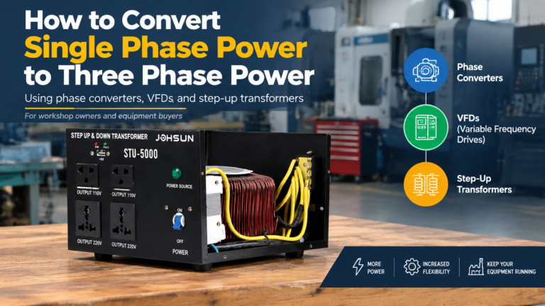
No. A transformer changes voltage but does not create the missing phases. A properly engineered phase converter or drive is required for that function.
Why is a three-phase autotransformer often smaller?
Part of the power transfers conductively through the common winding, reducing the winding material needed for the transformed portion. The benefit is greatest when the input and output voltages are close.
What does the 3 phase auto transformer symbol show?
It shows three shared winding paths or a simplified three-phase autotransformer representation, along with taps and connection information. A generic symbol does not replace the model-specific wiring diagram.
What information is needed for a quotation?
Provide input/output voltage, phase, frequency, kVA or current, load type, neutral requirement, tap range, duty cycle, enclosure, environment, standards, and order quantity through the JOHSUN contact page.
A control transformer steps a 380 V or 480 V supply down to the 120 V or 24 V that relays, contactor coils and PLC inputs run on. Learn how it works, why inrush VA — not sealed VA — sets the rating, and how to size, tap, fuse and ground one.
A practical guide to transformer live and neutral wiring: how to identify L and N terminals, connect them correctly, and avoid the hidden shock hazards of a reversed input.