Funcionamiento y cableado del autotransformador trifásico
Publicado: Autor: Lisa
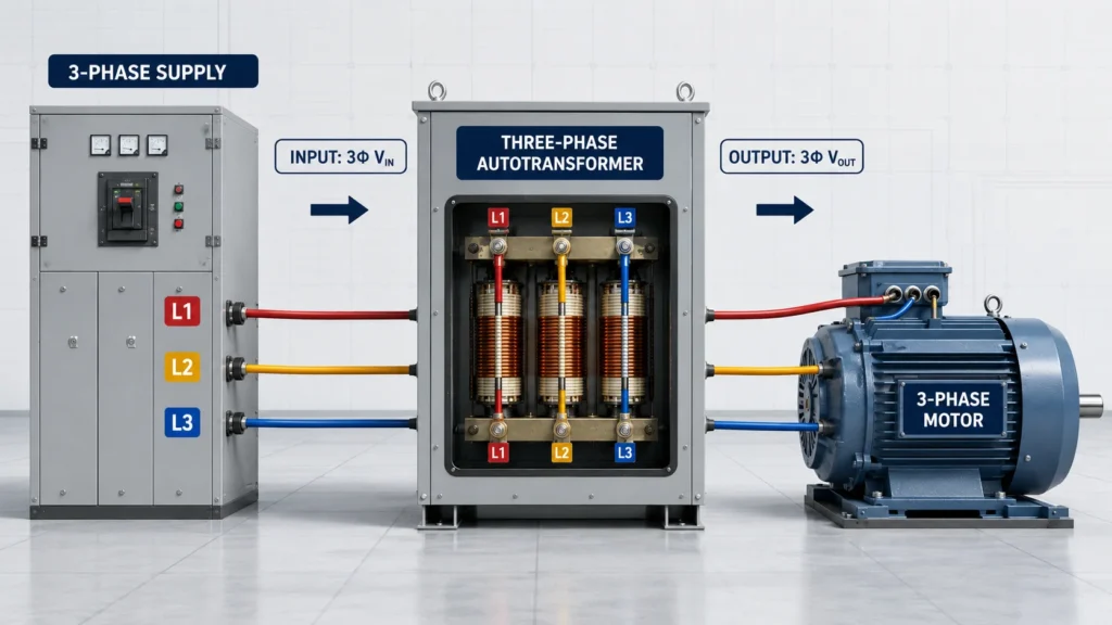
A autotransformador trifásico modifica la tensión de una alimentación de CA trifásica, manteniendo las tres fases conectadas eléctricamente a través de bobinados compartidos. Su función principal es elevar o reducir la tensión de forma eficiente cuando no se requiere aislamiento galvánico. Dado que parte de cada devanado es común tanto a la entrada como a la salida, el diseño puede utilizar menos cobre y material de núcleo que un transformador comparable de dos devanados, especialmente cuando las tensiones de entrada y salida son relativamente próximas.
Los autotransformadores trifásicos se utilizan para la adaptación de tensión industrial, el arranque de motores, la corrección de tensión, las pruebas de equipos y la distribución de energía. Esta guía explica su principio de funcionamiento, su construcción, su símbolo, el esquema de cableado, sus ventajas, sus limitaciones y la información que debe facilitar el comprador antes de seleccionar una unidad.
¿Cuál es la función de un autotransformador trifásico?
La función principal de un autotransformador trifásico es convertir un nivel de tensión de corriente alterna trifásica en otro sin modificar la frecuencia de alimentación. En función de las tomas de sus devanados y de la disposición de sus terminales, puede funcionar como dispositivo elevador o reductor de tensión.
Entre las funciones más habituales se incluyen:
Adaptación de tensión: adaptar la potencia de la instalación a la maquinaria o los equipos importados diseñados para otra tensión nominal.
Corrección de tensión de baja relación: la conversión entre tensiones como 380 V, 400 V y 415 V.
Arranque del motor: reducir temporalmente la tensión aplicada a un motor para limitar la corriente de arranque.
Asistencia para la distribución: conexión de sistemas trifásicos compatibles cuando el aislamiento eléctrico no forma parte de los requisitos de diseño.
Pruebas y puesta en servicio: suministrar una tensión trifásica determinada para cargas industriales compatibles.
Un autotransformador trifásico no genera energía trifásica a partir de una fuente monofásica, ni modifica la frecuencia. Además, normalmente no aísla la carga de la red eléctrica. Los autotransformadores de JOHSUN página de inicio ofrece una visión general de las familias de productos de transformadores y conversión de tensión para diferentes aplicaciones.
¿Cómo funciona un autotransformador trifásico?
El principio de funcionamiento se basa en la inducción electromagnética, combinada con una conexión conductiva directa a través del devanado compartido. Cada fase cuenta con un devanado con una o más tomas. La entrada se conecta a una parte del devanado, mientras que la carga se conecta a otra parte.
Una alimentación de corriente alterna trifásica alimenta los devanados trifásicos.
La corriente alterna produce flujos magnéticos desfasados en 120 grados eléctricos.
El flujo magnético induce una tensión a lo largo de cada devanado en función del número de espiras activas.
Las tomas seleccionadas determinan la relación entre la tensión de entrada y la de salida.
La potencia llega a la carga en parte por inducción y en parte a través de la sección conductora común del devanado.
Para un devanado ideal, la relación de tensión sigue a la relación de espiras. Si la salida utiliza menos espiras efectivas que la entrada, la tensión se reduce. Si utiliza más espiras, la tensión aumenta. En los equipos reales, también deben tenerse en cuenta las pérdidas en los devanados, el aumento de temperatura, la regulación, el factor de potencia de la carga y la corriente admisible.
Importante: La entrada y la salida de un autotransformador están conectadas eléctricamente. Una tensión de salida inferior no debe considerarse segura al tacto ni aislada de la red eléctrica.
Construcción de sistemas de autotransformadores trifásicos
En Construcción de un autotransformador trifásico Los equipos suelen seguir uno de estos dos enfoques: un conjunto de tres autotransformadores monofásicos o una unidad trifásica integrada. Ambos enfoques proporcionan una función de bobinado de autotransformador por fase.
Conjunto de transformadores de tres unidades
Se pueden conectar tres unidades monofásicas para formar un banco trifásico. Esta configuración puede simplificar el transporte, el mantenimiento y la sustitución de unidades de repuesto. También puede ofrecer flexibilidad de instalación para proyectos de gran capacidad, aunque normalmente requiere más interconexiones y espacio en el suelo.
Unidad trifásica integrada
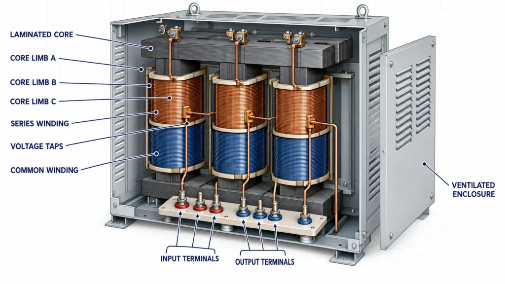
Un diseño integrado sitúa los devanados trifásicos en un núcleo magnético laminado común dentro de una única carcasa. Puede resultar más compacto y económico, con menos conexiones externas. El núcleo, los conductores de los devanados, el sistema de aislamiento, los terminales, el circuito de refrigeración, la carcasa, las tomas, los dispositivos de protección y la clase de temperatura se seleccionan en función de los kVA y el régimen de funcionamiento requeridos.
Elemento constructivo
Función
Comprobación del comprador
Núcleo magnético laminado
Proporciona una trayectoria controlada para el flujo magnético trifásico
Tipo de núcleo, ruido, pérdidas y aumento de temperatura
Bobinados compartidos
Sirven como secciones comunes y en serie para la conversión de tensión
Material del conductor, clase de aislamiento y intensidad nominal
Tomas de tensión
Establece la relación de entrada/salida o permite su ajuste
Rango de derivaciones, tamaño del paso y si las derivaciones están fuera de circuito
Terminales
Conecta la alimentación, la carga, el neutro (si lo hay) y la toma de tierra de protección.
Marcas, secuencia de fases, tamaño de las patillas y protección de acceso
Refrigeración y carcasa
Regula la temperatura y protege los componentes internos
Uso en interiores y exteriores, índice de protección IP, caudal de aire y límites ambientales
Cómo interpretar el símbolo de un autotransformador trifásico
A Símbolo del autotransformador trifásico muestra tres recorridos de devanado de un autotransformador o una representación trifásica simplificada. A diferencia del símbolo de un transformador de aislamiento, las conexiones de entrada y salida se muestran en el mismo devanado, en lugar de en dos bobinas separadas.
En los planos, fíjate en estos detalles:
Conductores trifásicos, que suelen identificarse como L1, L2 y L3 o A, B y C.
Tomas de entrada y salida conectadas a los mismos devanados de fase.
Una conexión en estrella o en Y cuando el diseño incluye un neutro común.
Notación de conexión en triángulo o en estrella, cuando proceda.
Relaciones de tensión, potencia nominal en kVA, frecuencia, posiciones de las tomas e identificadores de los terminales.
Un símbolo de toma de tierra de protección conectado a la carcasa, que está separado del conjunto de bobinados del circuito.
Un diagrama de una sola línea puede representar las tres fases con una sola línea, mientras que un esquema o plano de conexiones muestra todos los conductores y bornes. Nunca deduzcas la disposición física de los bornes basándote únicamente en un símbolo genérico; utiliza la placa de características del fabricante y el plano de conexiones específico del modelo.
Explicación del esquema de cableado de un autotransformador trifásico
A Esquema de cableado de un autotransformador trifásico identifica las tres líneas de entrada, las derivaciones de salida correspondientes, cualquier punto neutro, la toma de tierra de protección, las conexiones entre derivaciones y los dispositivos de protección. Los nombres exactos de los terminales varían según el fabricante y el modelo, por lo que el diagrama suministrado con el equipo es el documento de referencia.
Una configuración conceptual simplificada con conexión en estrella puede describirse de la siguiente manera:
Alimentación trifásica. Autotransformador. Carga trifásica
L1 ------------------------------- bobinado de la fase A/toma ---------------- T1
L2 ------------------------------- bobinado de la fase B/toma ---------------- T2
L3 ------------------------------- bobinado/toma de la fase C ---------------- T3
punto neutro en estrella ---------------- N, si está previsto
Toma de tierra de protección -------------------- carcasa metálica ----------------- PE
Se trata de un esquema explicativo, no de un diagrama de instalación. Antes de poner en tensión una unidad, un electricista cualificado debe comprobar la tensión indicada en la placa de características, la secuencia de fases, las conexiones de derivación, la disposición del neutro, el método de puesta a tierra, la protección contra sobrecorrientes, el calibre de los conductores, los valores de par de apriete y la resistencia de aislamiento.
Tres errores habituales en el cableado son invertir los bornes de entrada y salida previstos sin autorización, dar por sentado que cualquier punto de la estrella puede utilizarse como neutro y confundir la toma de tierra de protección con el neutro del circuito. Las conexiones incorrectas de las tomas pueden exponer a los equipos a una tensión inadecuada o provocar una corriente excesiva en el devanado.
Funcionamiento de los transformadores elevadores y reductores
A Transformador elevador y reductor se define por la relación entre la tensión aplicada y la tensión de salida. En un autotransformador, un mismo devanado puede admitir en ocasiones ambos sentidos, pero nunca debe darse por sentada la reversibilidad sin una confirmación por escrito del fabricante.
Modo de funcionamiento
Relación de tensión
Uso trifásico típico
Reductor
La tensión de salida es inferior a la de entrada
Alimentación de equipos industriales de baja tensión desde una red de distribución de la central de alta tensión
Step-up
La tensión de salida es superior a la de entrada
Adaptación de una fuente de alimentación de menor tensión a maquinaria compatible de mayor tensión
Corrección de buck/boost
La producción difiere de la producción inicial en un porcentaje relativamente pequeño
Corrección de un ligero desajuste de tensión entre la instalación y el equipo
Para conversiones con relaciones de transformación pequeñas, el uso de un autotransformador puede resultar especialmente eficiente en cuanto al material. Para relaciones de transformación grandes, necesidades especiales de puesta a tierra, cargas sensibles o cualquier aplicación que requiera separación eléctrica, un transformador de aislamiento de dos devanados puede ser la mejor opción desde el punto de vista técnico.
Autotransformador trifásico frente a transformador de aislamiento
Característica
Autotransformador trifásico
Transformador de aislamiento trifásico
Relación sinuosa
Secciones de devanado compartidas de entrada y salida
Los devanados primario y secundario están separados
Aislamiento galvánico
No
Sí, siempre que se haya diseñado e instalado correctamente
Tamaño habitual y materiales utilizados
A menudo es menor cuando la relación de tensión es baja
Suele ser mayor para el mismo kVA
Flexibilidad en la conexión a tierra
Limitado por la relación entre entrada y salida conductiva
Se puede establecer un sistema secundario independiente cuando esté permitido
La mejor opción
Adaptación eficiente de tensión sin aislamiento
Aislamiento, control de puesta a tierra y separación eléctrica
¿Dónde se utilizan los autotransformadores trifásicos?
Fábricas en las que se conecta la maquinaria a una tensión de la instalación que difiere ligeramente de la indicada en la placa de características del equipo.
Circuitos de arranque de motores que reducen la tensión en los bornes durante la aceleración.
Sistemas de climatización, bombas, compresores, calentadores y equipos de proceso, una vez confirmada su idoneidad para la carga.
Proyectos de distribución comercial e industrial en los que no se requiere aislamiento.
Estaciones de ensayo que requieran una conversión de tensión trifásica fija o con toma de derivación.
El tipo de carga es importante. Los motores presentan una corriente de arranque, mientras que los variadores de frecuencia, los rectificadores, los sistemas SAI y otras cargas no lineales pueden generar armónicos y un calentamiento adicional. Estas características deben tenerse en cuenta durante el dimensionamiento, en lugar de basarse únicamente en la potencia nominal en kW del equipo.
Cómo dimensionar y especificar un autotransformador trifásico
La potencia de un transformador trifásico se suele expresar en kVA. Un cálculo inicial habitual es el siguiente:
kVA = 1,732 × tensión de línea × corriente de línea ÷ 1000
El cálculo es solo un punto de partida. La clasificación final debe tener en cuenta la corriente continua, la corriente de arranque, el factor de potencia de la carga, los armónicos, la temperatura ambiente, la altitud, la ventilación, el ciclo de trabajo y el margen de seguridad aplicable.
Indica las tensiones entre fases de entrada y salida.
Comprueba la frecuencia trifásica y si se necesita un neutro.
Indique la corriente continua máxima o la carga en kVA.
Identifica motores, variadores de frecuencia, rectificadores, cargas de SAI, calefactores u otros tipos de carga.
Especifique las tomas, el rango de regulación, la carcasa, el entorno (interior o exterior) y la refrigeración.
Indique las normas exigidas, el aumento de temperatura, la clase de aislamiento, el grado de protección, los terminales y los accesorios.
Para una unidad trifásica diseñada específicamente para este fin, utilice la de JOHSUN Servicio ODM/OEM para analizar las especificaciones eléctricas y mecánicas completas. La información general sobre la empresa y el ámbito de fabricación está disponible en la Página «Quiénes somos» de JOHSUN.
Utiliza un autotransformador trifásico adecuado para cada trabajo
Un autotransformador trifásico es una solución eficaz para la conversión de tensión cuando tanto la fuente como la carga son trifásicas, la relación de tensión requerida es adecuada y no se necesita aislamiento galvánico. Su diseño de devanado compartido permite reducir el tamaño y el consumo de material, pero ese mismo diseño plantea la limitación más importante: la carga permanece conectada eléctricamente a la fuente de alimentación.
Elige la unidad teniendo en cuenta los requisitos completos del sistema, y no solo la tensión. Es fundamental tener en cuenta la potencia correcta en kVA, el comportamiento de la carga, las necesidades de neutro y puesta a tierra, las tomas de derivación, la carcasa, la refrigeración, la protección y la documentación de instalación para garantizar un resultado seguro y fiable.
Preguntas frecuentes
¿Proporciona aislamiento un autotransformador trifásico?
No. Su entrada y su salida comparten secciones de bobinado conductoras. Si el sistema requiere aislamiento galvánico, elija un transformador de dos bobinados adecuado.
¿Puede funcionar tanto como transformador elevador como reductor?
Algunos modelos pueden funcionar en cualquier sentido, pero es necesario confirmar los terminales, las tomas, la corriente, la configuración de la puesta a tierra y la regulación de tensión permitidos para el modelo concreto.
¿Puede un autotransformador convertir la corriente monofásica en trifásica?
No. Un transformador modifica la tensión, pero no genera las fases que faltan. Para esa función se necesita un convertidor de fases o un variador diseñado adecuadamente.
¿Por qué los autotransformadores trifásicos suelen ser más pequeños?
Parte de la potencia se transmite por conducción a través del devanado común, lo que reduce la cantidad de material de devanado necesaria para la parte transformada. La ventaja es mayor cuando las tensiones de entrada y salida son similares.
¿Qué representa el símbolo del autotransformador trifásico?
Muestra tres trayectorias de devanado compartidas o una representación simplificada de un autotransformador trifásico, junto con las tomas y la información de conexión. Un símbolo genérico no sustituye al esquema de cableado específico del modelo.
¿Qué datos se necesitan para elaborar un presupuesto?
Indique la tensión de entrada/salida, la fase, la frecuencia, los kVA o la corriente, el tipo de carga, los requisitos del neutro, el rango de tomas, el ciclo de trabajo, la carcasa, las condiciones ambientales, las normas y la cantidad del pedido a través del Página de contacto de JOHSUN.
Transformador de 230 V a 110 V para España: conformidad con la norma REBT, ITC-BT-18 e ITC-BT-24, puesta a tierra del secundario y documentación conforme a la norma UNE-EN IEC 61558.
Transformador de 230 V a 110 V para los Países Bajos: norma NEN 1010, normas sobre dispositivos de protección contra fugas a tierra de 30 mA, diferencia entre «aardlekschakelaar» y «aardlekautomaat», y puesta a tierra secundaria.
Transformador de 230 V a 110 V para Francia: NF C 15-100, puesta a tierra TT, protección diferencial de 30 mA y cuándo conectar a tierra el secundario.