Explicación y uso del diagrama del símbolo del autotransformador
Publicado: Autor: Lisa
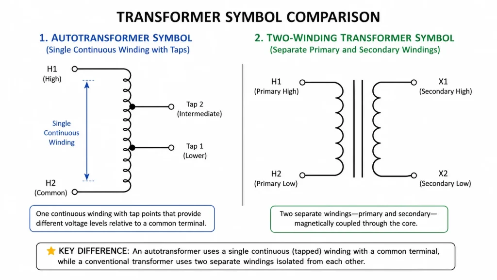
En autotransformador El símbolo es la representación gráfica que se utiliza en los diagramas de circuitos y en los esquemas eléctricos para identificar un autotransformador. A diferencia del símbolo convencional del transformador de dos devanados, el símbolo del autotransformador utiliza un único devanado continuo con una o más conexiones de toma, lo que transmite visualmente su diseño de bobina compartida, sin devanados primario y secundario separados.
Saber interpretar correctamente este símbolo es fundamental para cualquiera que trabaje con esquemas eléctricos, ya sea para diseñar un cuadro de arranque de motores, revisar un esquema de distribución eléctrica o buscar un transformador para un proyecto. Esta guía explica qué es el Johsun Tec cómo es el símbolo de un autotransformador, en qué se diferencia de los símbolos de otros transformadores, las principales diferencias entre los tipos monofásicos, trifásicos y variables, y cómo interpretarlo en un esquema de circuito real.
¿Qué es el símbolo del autotransformador?
En los esquemas eléctricos, el símbolo del autotransformador consiste en un único símbolo de bobinado en espiral —que suele representarse como una serie de bucles semicirculares o una espiral continua— con uno o más puntos de toma marcados a lo largo de su extensión. El símbolo también puede incluir una representación del núcleo (dos líneas paralelas) para indicar un diseño con núcleo de hierro, o bien puede omitir las líneas del núcleo en el caso de los transformadores con núcleo de aire o en los esquemas simplificados.
La característica que distingue el símbolo del autotransformador del símbolo del transformador convencional es la ausencia de símbolos distintos para las bobinas primaria y secundaria. En su lugar, un único símbolo de devanado representa tanto la entrada como la salida, con tomas que indican dónde se toma o se aplica la tensión. Esto refleja directamente la estructura física de un autotransformador, en el que un devanado continuo actúa tanto como circuito primario como secundario.
Para comprender mejor cómo funcionan los autotransformadores, consulta nuestra guía sobre qué es un autotransformador.
Símbolo del autotransformador frente al símbolo del transformador convencional
La forma más rápida de distinguir un autotransformador de un transformador convencional en cualquier esquema es fijarse en el número de bobinados independientes que aparecen representados. La tabla siguiente resume las diferencias visuales.
Característica visual
Símbolo del autotransformador
Símbolo de un transformador convencional
Número de vueltas
Un bobinado continuo
Dos devanados independientes (primario y secundario)
Puntos de toque
Una o varias tomas a lo largo del devanado
No hay puntos comunes entre los devanados
Símbolo central
Dos líneas paralelas situadas entre o junto a la espiral
Dos líneas paralelas entre los devanados
Conexión eléctrica
El devanado es continuo: la entrada y la salida comparten el conductor
No hay conexión eléctrica directa entre el primario y el secundario
Puntos de polaridad
Puede aparecer en los extremos de los devanados o en los puntos de derivación
Suelen aparecer al principio de cada bobinado independiente
Estilo de dibujo habitual
Una línea en espiral o en bucle con una flecha o una marca de conexión en el punto de unión
Dos conjuntos independientes de bucles, que suelen dibujarse en lados opuestos del núcleo
Esta distinción es importante en la práctica: si ves dos símbolos de bobinas separadas con un núcleo entre ellas, el esquema representa un transformador de aislamiento convencional. Si ves una bobina continua con una toma, se trata de un autotransformador, y no hay aislamiento galvánico entre la entrada y la salida.
Diagrama del símbolo de un autotransformador monofásico
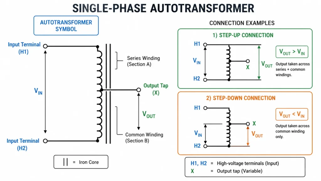
El símbolo del autotransformador monofásico es el más básico. Consiste en un devanado continuo representado como una serie de bucles a lo largo de un núcleo, con al menos tres puntos de conexión eléctrica: dos terminales en los extremos y una toma intermedia.
Símbolo del autotransformador elevador
En una configuración elevadora, la entrada se conecta a una parte del devanado (menos espiras), y la salida se toma de todo el devanado (más espiras). El símbolo refleja esto: los cables de entrada se conectan a un punto de toma y a uno de los extremos, mientras que los cables de salida se conectan a ambos extremos del devanado completo.
Características clave de los símbolos para el paso ascendente:
El punto de derivación está más cerca de uno de los extremos del devanado
La conexión de salida abarca más espiras del devanado que la de entrada
Pueden aparecer marcas en forma de flecha o etiquetas (H1, H2 para el lado de alta tensión; X1, X2 para el lado de baja tensión)
Símbolo del autotransformador reductor
En una configuración reductora, la entrada se conecta a través de todo el devanado (más espiras), y la salida se toma de un punto de derivación (menos espiras). El símbolo muestra la entrada conectada a toda la bobina y la salida conectada entre un extremo y una derivación intermedia.
Características clave de los símbolos para la reducción de tensión:
La entrada abarca toda la longitud del símbolo del devanado
La salida se conecta por un extremo a un punto de derivación dentro del devanado
Las etiquetas de tensión en cada terminal aclaran la relación
En muchos esquemas no se indica explícitamente la dirección; esta se deduce a partir de los valores de tensión que figuran junto a los terminales. Una buena regla general: el lado con menos espiras tiene la tensión más baja.
Three-Phase Auto Transformer Symbol
A three-phase autotransformer symbol represents three single-phase autotransformer units or a single three-limb core with shared windings. In a schematic, the symbol typically shows three identical autotransformer winding symbols arranged in either a star (wye) or delta configuration.
The most common three-phase autotransformer symbol uses a star connection — three windings connected at a common neutral point, with each winding drawn as a continuous coil with a tap. The delta-connected variant shows the windings arranged in a closed triangle.
Connection Type
Symbol Appearance
Uso típico
Star (Y) autotransformer
Three windings originating from a common neutral point, each with a series winding and tap
Transmission interconnection, distribution voltage regulation
Delta autotransformer
Three windings connected end-to-end in a closed loop, each with a tap
Industrial motor starting, phase balancing
Zigzag autotransformer
Interconnected winding segments drawn in a zigzag pattern
Grounding transformers, harmonic mitigation
On a three-phase autotransformer symbol, look for the common neutral point in star connections — it is a key indicator that distinguishes it from a conventional three-phase transformer symbol, where star windings on the primary and secondary sides are electrically separate.
Variable Autotransformer (Variac) Symbol
A variable autotransformer — commonly known by the trade name Variac — uses a slightly different symbol to indicate its adjustable output. The standard symbol for a variable autotransformer shows a single winding with an arrow drawn diagonally across the coil, representing the sliding contact or wiper arm that moves along the winding to select the output voltage.
The arrow typically points toward the center of the winding and may have a separate terminal label. This is the standard IEC and ANSI convention for any variable or tapped inductive component.
In addition to the arrow, the symbol may include:
A circular enclosure around the winding to represent a toroidal core
Labels for input (LINE) and output (LOAD)
A grounding symbol at one end of the winding
Variable autotransformers are commonly drawn in laboratory power supply schematics, test bench wiring diagrams, and voltage adjustment circuits.
IEC vs ANSI Symbol Standards
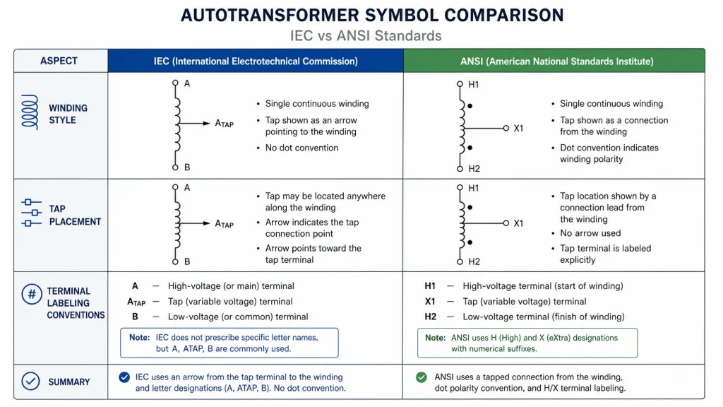
Electrical symbols are not universal — two major standards bodies define how autotransformer symbols should be drawn. Understanding the differences helps you read schematics from different regions and manufacturers correctly.
Aspecto
IEC 60617 (International)
ANSI/IEEE Std 315 (North America)
Winding style
Semicircular loops (scallops)
Continuous spiral or sine-wave curves
Step-up/down distinction
Indicated by tap position and voltage labels
Often drawn with longer winding on the high-voltage side
Variable arrow
Arrow at 45 degrees crossing the winding
Arrow crossing the winding symbol similarly
Core representation
Two solid parallel lines
Two solid parallel lines (same convention)
Phase marking
U, V, W or L1, L2, L3
A, B, C or H1-H2, X1-X2
In practice, most modern schematics follow a hybrid approach. The key takeaway is that regardless of the standard, an autotransformer is always recognizable by its single coil with a tap — the stylistic details (loop shape, phase labels) vary by region but the underlying meaning is the same.
How to Read an Autotransformer Symbol in a Circuit Diagram
When you encounter an autotransformer symbol in a practical circuit diagram, follow these steps to interpret it correctly:
Identify the symbol type. Confirm it is an autotransformer — one continuous winding with a tap — not a conventional transformer with two separate windings.
Locate the input and output terminals. Check the voltage labels or terminal markings. The terminals connected across the full winding are the higher-voltage side; those connected across a portion are the lower-voltage side.
Determine step-up or step-down. If the input connects to a partial winding and output spans the full winding, it is a step-up. If input spans the full winding and output uses a tap, it is a step-down.
Check the phase configuration. For three-phase symbols, identify whether the windings are arranged in star or delta. Look for the neutral point in star configurations.
Note the core type. Two parallel lines indicate an iron core (typical for power autotransformers). No lines indicate an air-core design (rare, typically for high-frequency applications).
Look for the variable arrow. If an arrow crosses the winding, the output voltage is adjustable — this is a variable autotransformer or Variac.
Review the nameplate data. In equipment schematics, the symbol is often accompanied by kVA rating, voltage ratio, and frequency. Match these to your requirements.
If you are selecting an autotransformer for an actual project, recognizing the symbol is the first step. The next is matching the right model to your load. Browse our DT/ST Series autotransformers for fixed-ratio voltage conversion or ponte en contacto con nuestro equipo for custom winding specifications.
The auto transformer symbol is a simple but informative graphic that communicates the core design principle of the autotransformer at a glance: one winding, shared by input and output, with taps that define the voltage relationship. Whether you are reading a power system schematic, a motor control drawing, or a product datasheet, recognizing this symbol — and the variations for single-phase, three-phase, step-up, step-down, and variable types — helps you make faster, more accurate decisions. For more on interpreting transformer symbols across different types, see our transformer symbols guide.
PREGUNTAS FRECUENTES
What does an autotransformer symbol look like?
An autotransformer symbol shows a single continuous winding — typically drawn as a series of semicircular loops — with one or more tap points along the coil and two parallel lines representing the iron core. It lacks the separate primary and secondary windings found in a conventional transformer symbol.
How can you tell the difference between an autotransformer and a conventional transformer on a schematic?
Count the windings. If there is one continuous coil with a tap, it is an autotransformer. If there are two separate sets of coils on opposite sides of the core, it is a conventional transformer. The autotransformer symbol never shows electrically separate primary and secondary windings.
Does the autotransformer symbol indicate whether it is step-up or step-down?
Not inherently — the same symbol is used for both. The direction is determined by how the terminals are connected: input across a tap and one end (step-up) vs input across the full winding (step-down). Voltage labels next to the terminals clarify the ratio in a complete schematic.
What is the symbol for a variable autotransformer?
A variable autotransformer symbol adds a diagonal arrow crossing the winding, representing the sliding contact or wiper. This arrow distinguishes it from a fixed-ratio autotransformer and indicates that the output voltage is continuously adjustable.
Are autotransformer symbols the same in IEC and ANSI standards?
The underlying concept is the same — a single winding with a tap — but the drawing style differs. IEC uses semicircular loops (scallops), while ANSI uses a continuous spiral or sine-wave curve. Terminal phase labels also differ: IEC uses U/V/W or L1/L2/L3, ANSI uses A/B/C or H1-H2/X1-X2.
How is a three-phase autotransformer drawn in a schematic?
A three-phase autotransformer is drawn as three single autotransformer winding symbols connected in star (wye) or delta configuration. In a star connection, all three windings share a common neutral point. The symbol may also show a tertiary delta winding for harmonic suppression in large power autotransformers.
Transformador de 230 V a 110 V para España: conformidad con la norma REBT, ITC-BT-18 e ITC-BT-24, puesta a tierra del secundario y documentación conforme a la norma UNE-EN IEC 61558.
Transformador de 230 V a 110 V para los Países Bajos: norma NEN 1010, normas sobre dispositivos de protección contra fugas a tierra de 30 mA, diferencia entre «aardlekschakelaar» y «aardlekautomaat», y puesta a tierra secundaria.
Transformador de 230 V a 110 V para Francia: NF C 15-100, puesta a tierra TT, protección diferencial de 30 mA y cuándo conectar a tierra el secundario.