How to Test the Transformer Turns Ratio: A Step-by-Step Guide
Publié le : Auteur : Lisa
A transformer turns ratio test is the fastest way to confirm that the unit in front of you is the unit on the nameplate. It takes about fifteen minutes, needs a variable AC source and two multimeters, and catches three failures that quietly ruin low voltage installations: swapped windings, shorted turns and a mis-set tap. This guide covers the applied-voltage method used on transformateurs basse tension from 100 VA to 10 kVA, shows the arithmetic, and explains when a dedicated ratio tester earns its price. Transformer testing does not need to be complicated to be useful.
What the Transformer Ratio Test Actually Checks
The turns ratio is primary turns divided by secondary turns. Since voltage per turn is the same on both windings, it also equals the voltage ratio:
N1 / N2 = V1 / V2 = I2 / I1
A transformer marked 220 V / 110 V should produce a ratio of 2.000: apply 100 V to the primary and a healthy unit delivers 50 V. Winding construction sets that ratio, so a drift from the nameplate is physical evidence of a winding problem. The test answers three questions:
Is the unit the model that was ordered, or was it mislabelled or rewound?
Are there shorted turns inside either winding?
Do all three phases of a three-phase unit agree?
It does pas measure insulation health, core loss or temperature rise, so it is one entry in a test schedule.
What You Need Before You Start
Safety first. On a small transformer it is easy to get careless because the voltages look harmless, so treat every winding as live until proved otherwise. Isolate and lock out every source, ground the windings, disconnect downstream loads, and wear insulated gloves and glasses even at 110 V.
For the test itself you need a variable AC source, two true-RMS multimeters and short test leads.
Objet
Objectif
Note
Variable AC source (variac)
Sets a safe, adjustable primary voltage
A 0-250 V, 0.5-5 kVA variable autotransformer covers most bench work
Two true-RMS multimeters
Read primary and secondary simultaneously
True-RMS matters; averaging meters misread on distorted waveforms
Test leads with fused probes
Safe connection to terminals
Keep leads short to reduce pickup
Nameplate data or datasheet
Supplies the expected ratio
Record rated voltages and tap schedule before you connect anything
The Applied-Voltage Method Without a TTR Tester
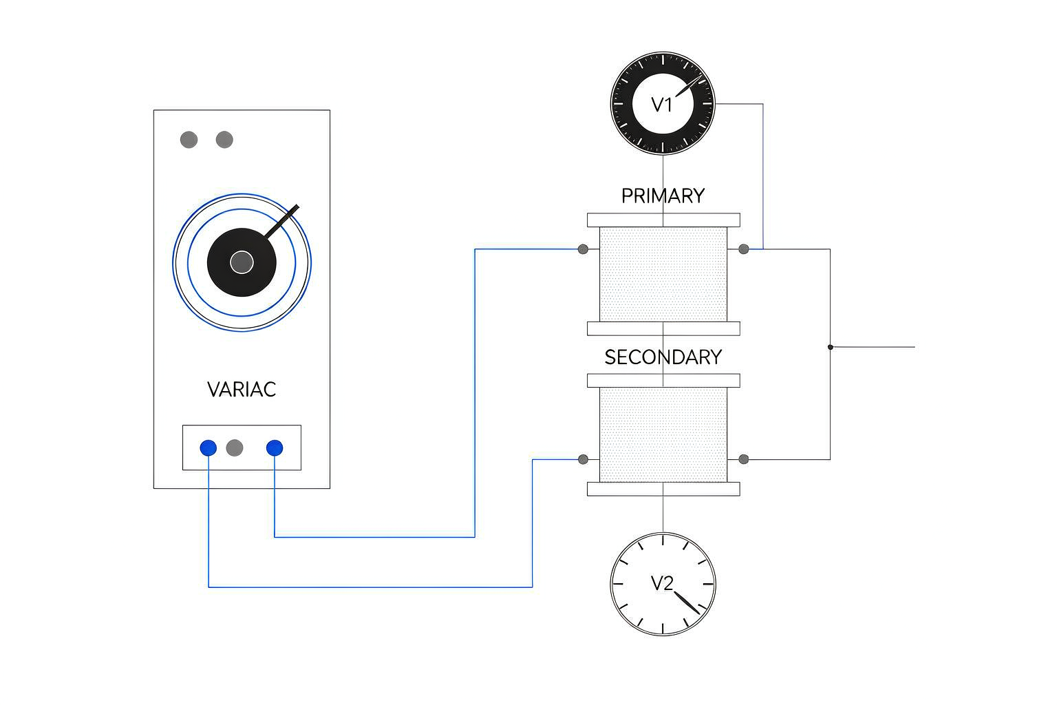
This is the standard bench method for small transformers: you control the primary voltage and calculate the ratio from two simultaneous voltmeter readings.
Step 1 – Identify the windings
Read the nameplate for rated primary and secondary voltage and tap schedule, then divide primary by secondary to get the expected ratio – 2.000 for 220 V / 110 V, 1.727 for 380 V / 220 V. Write it down before you touch a terminal; every reading is judged against it.
Step 2 – Connect the variac and meters
Feed the variac from a protected supply and connect its output to the transformer primary. Put meter one across the variac output and meter two across the secondary. Both must be on AC volts and a fixed range, because auto-ranging mid-measurement shows as a false dip.
Step 3 – Set a safe test voltage
Wind the variac up slowly to 20 to 50 percent of rated primary voltage – for a 220 V primary, 50 to 100 V. That is enough for a stable reading without stressing insulation. Never exceed the rated primary voltage.
Step 4 – Read both meters together
Most bad results come from here. Let the voltage settle, then read both meters at the same moment. If the secondary drifts, a lead is making poor contact. Repeat twice; readings within half a percent are trustworthy.
Step 5 – Calculate the ratio
Divide primary voltage by secondary voltage. That is the measured ratio.
Measured ratio = Vprimary / Vsecondary
Step 6 – Record the result
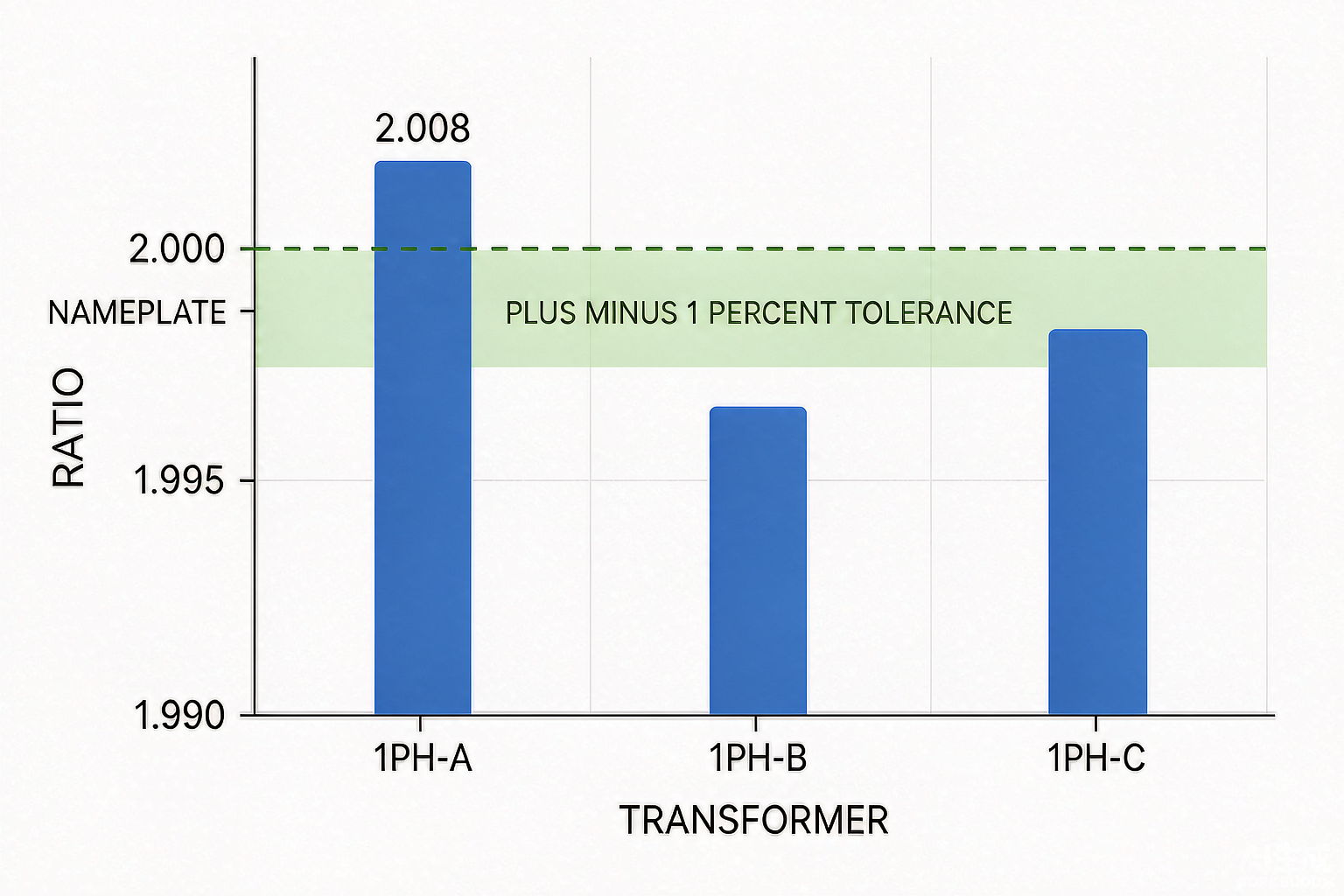
Record the applied voltage, secondary voltage, measured ratio, nameplate ratio and percentage error – five fields worth more than a pass/fail tick. Worked example: on a 1000 VA, 220 V / 110 V transformer, meter one reads 100.0 V and meter two reads 49.8 V, so the measured ratio is 2.008 against a nameplate ratio of 2.000.
Étape
Action
Record
1
Read nameplate, compute expected ratio
Expected ratio, tap position
2
Connect variac to primary, meters to both windings
Winding identified as primary
3
Raise to 20-50% of rated primary voltage
Applied voltage
4
Read both meters simultaneously, twice
Vprimary, Vsecondary
5
Divide primary by secondary
Measured ratio
6
Compare with nameplate, compute error
Ratio error in percent
How to Calculate Ratio Error and Tolerance
Ratio error is how far the measured ratio sits from the nameplate ratio, as a percentage:
Ratio error (%) = (Measured ratio – Nameplate ratio) / Nameplate ratio x 100
In the example above, (2.008 – 2.000) / 2.000 x 100 = +0.4 percent. A positive number means the primary has relatively more turns than expected, or the secondary fewer. Acceptance limits are not universal: they depend on the transformer class, the standard specified and the manufacturer’s tolerance. The bands below suit low voltage dry-type units, but the datasheet always wins.
Transformer class
Typical acceptable ratio deviation
Comment
Small dry-type LV transformer (100 VA – 10 kVA)
+/- 1%
Winding and measurement scatter both contribute
General purpose LV transformer, closer tolerance build
+/- 0.5%
Specified for control and instrumentation duty
Measurement or instrument transformer
+/- 0.1% to +/- 0.5%
Class-dependent, verified with a calibrated ratio bridge
If a unit lands just outside the band, repeat the measurement before condemning it. Lead placement, meter accuracy and waveform distortion can each account for a few tenths of a percent.
Testing the Ratio on a Three-Phase Transformer
Three-phase testing adds two complications: test every phase, and know whether the nameplate voltages are line or phase values. A delta winding has no neutral, so comparing a line-to-line reading against a phase ratio produces an apparent error of exactly the square root of three. The three-phase transformer connection guide covers the terminal arrangements.
Test each phase pair separately: A-a, B-b, C-c.
Compare the three ratios against each other; spread between phases is often more revealing than absolute error.
On a wye-wye unit, phase voltage equals line voltage divided by 1.732.
On a delta-wye unit, apply the 1.732 factor deliberately and confirm against the nameplate.
One phase several percent off while the other two are clean points at a fault in that phase winding, not the transformer as a whole – which decides repair versus scrap.
Using a Dedicated Ratio Tester
A turns ratio tester, or TTR set, reports ratio, polarity, phase angle and sometimes excitation current in one pass, and calculates the error for you. It earns its place when you need vector group confirmation, fast testing across many taps, documented commissioning results, or phase angle measurement that two voltmeters cannot provide.
Consideration
Variac + two multimeters
Dedicated ratio tester
Measured quantities
Voltage ratio only
Ratio, polarity, phase angle, excitation current
Three-phase vector group
Not possible
Direct reading
Typical accuracy
0.2-0.5% with good meters
0.05-0.1%
Cost and setup
Low, uses existing bench gear
Higher, needs calibration and training
Best suited to
Single-phase bench checks and incoming inspection
Commissioning, tap verification, QA documentation
Checking Tap Positions and Variable Autotransformers
If the transformer has off-circuit taps, the ratio should change by the tap step at each position. A +/- 5 percent schedule on a 2.000 base ratio reads about 2.100 at +5 percent and 1.900 at -5 percent. Test every tap; one that reads correctly at nominal but wrong at the extremes usually means poor contact, not a winding fault.
A variable autotransformer is different: its brush moves along an exposed winding, so the ratio changes continuously. Testing one means checking that the output tracks the dial smoothly with no dead spots or jumps. A variable autotransformer with a pointer scale helps here, because the dial reading can be compared against the measured output across the full sweep.
The brush contact that makes a variac adjustable also makes it a possible source of erratic readings. If the secondary jumps while the primary reading is steady, suspect the variac before the transformer under test.
Common Mistakes That Skew Ratio Readings
Erreur
Symptom
Fix
Using an averaging meter
Reading 1-3% low on a distorted waveform
Use true-RMS instruments
Testing with the load still connected
Secondary reads low, error looks like a winding fault
Disconnect all downstream equipment
Comparing a line voltage against a phase ratio
Error of about 73% on a delta winding
Confirm line versus phase reference first
Auto-ranging during the measurement
Brief dip, unstable reading
Lock the meter range manually
Reading the meters at different moments
Random error of several percent
Read simultaneously, repeat twice
Over-volting to get a clearer reading
Insulation stress, heating, saturation
Stay at 20-50% of rated primary voltage
Measuring at the source, not the winding
Good unit rejected
Verify applied voltage at the winding terminals
How to Read a Ratio Result
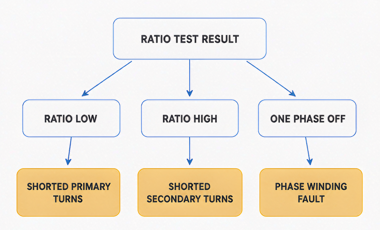
The pattern across phases, taps and time is what identifies the fault.
Observation
Likely cause
Next action
Measured ratio below nameplate
Shorted turns in the primary, or fewer primary turns than specified
Repeat test, then inspect for discolouration and burnt varnish
Measured ratio above nameplate
Shorted turns in the secondary
Compare with a DC resistance check on the same winding
One phase deviates, others clean
Phase winding fault or a bad internal connection
Treat as a winding failure; do not return to service
No secondary voltage at all
Open winding or broken connection
Continuity and resistance test to localise the break
Ratio changes smoothly with the tap
Normal tap behaviour
Record and trend over time
Ratio jumps erratically at one tap
Poor tap contact or misalignment
Clean and re-seat the tap, retest
Keeping a Ratio Test Record
A one-off check tells you whether the unit is good today; a trend tells you whether it is degrading. Keep four numbers per unit – applied voltage, secondary voltage, measured ratio and test date – alongside your insulation resistance readings and your DC resistance measurements of the transformer windings.
Repeat the test at incoming inspection, after any repair, and at your maintenance interval. If the ratio has moved beyond the datasheet tolerance, investigate before the unit returns to service. Load capacity is a separate calculation, which is why transformers are rated in kVA rather than kW.
Where to Go From Here
The turns ratio test is the cheapest high-value check available to anyone working with low voltage transformers. A variable source, two decent meters and fifteen minutes confirm that the unit transforms at the ratio it claims. Do it at incoming inspection so a wrong unit never reaches the panel.
If you are specifying a transformer and need the ratio, tap schedule and winding arrangement documented up front, browse the step up and step down transformer range or send your rated voltages and load details and we will match a unit to them.
FAQ
What is the turns ratio formula for a transformer?
The turns ratio equals primary turns divided by secondary turns, and it equals primary voltage divided by secondary voltage. A 220 V / 110 V transformer has a ratio of 2.000.
Can I test a transformer ratio with a multimeter?
Yes, on a low voltage transformer. Feed the primary from a variac set to 20 to 50 percent of rated voltage, read both windings with true-RMS multimeters at the same time, then divide primary volts by secondary volts. A resistance setting cannot measure ratio.
What is an acceptable turns ratio deviation?
For small dry-type low voltage transformers, plus or minus 1 percent is a practical working limit, and closer-tolerance builds are specified at plus or minus 0.5 percent. Confirm against the datasheet or the standard the unit was ordered to.
How do I test the ratio of a three-phase transformer?
Test each phase individually – A-a, B-b and C-c – and compare the results against each other and against the nameplate. Confirm whether the nameplate voltages are line or phase values first, because on a delta winding a line-to-line reading shows a false error of about 73 percent.
Do I need a special ratio tester for a 1 kVA transformer?
No. A variac and two true-RMS multimeters are sufficient for single-phase bench checks in the 100 VA to 10 kVA range. A dedicated tester becomes worthwhile when you need phase angle and polarity, a three-phase vector group check, or documented commissioning results.
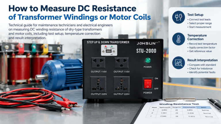
A practical guide to measuring the DC resistance of transformer windings and motor coils, covering four-wire setup, test current selection, temperature correction and pass/fail limits.
A control transformer steps a 380 V or 480 V supply down to the 120 V or 24 V that relays, contactor coils and PLC inputs run on. Learn how it works, why inrush VA — not sealed VA — sets the rating, and how to size, tap, fuse and ground one.
A practical guide to transformer live and neutral wiring: how to identify L and N terminals, connect them correctly, and avoid the hidden shock hazards of a reversed input.