A transformer sitting energized with nothing connected to its secondary is still consuming power. That consumption is transformer no-load loss — energy burned inside the magnetic core every hour the unit is switched on, regardless of load. On one 1 kVA unit the figure looks trivial. Across a plant running dozens of units around the clock for twenty years, it becomes a real line item on the electricity bill.
This guide covers what no-load loss is, what causes it, how to calculate it, and whether a lower-loss core justifies its higher price.
What Is No-Load Loss in a Transformer?
No-load loss is the active power a transformer absorbs when rated voltage and frequency are applied to the primary winding while the secondary is left open-circuit. It is also called core loss or iron loss, and the terms are interchangeable.
Two properties define it. It is continuous, beginning the moment the unit is energized and persisting at every load level. And it is independent of load current, tracking only voltage, frequency, flux density and core material. Because no-load current is typically just 1–3% of rated current, primary winding loss at no load is negligible, so a no-load wattmeter reading is effectively the core loss.
No-Load Loss vs. Load Loss
Load loss — copper loss — appears when current flows through the windings, and it behaves in the opposite way.
| Property |
No-Load Loss (Core Loss) |
Load Loss (Copper Loss) |
| Location |
Magnetic core |
Windings and structural parts |
| Depends on |
Voltage, frequency, flux density, core material |
Load current, winding resistance, temperature |
| Behaviour |
Constant at all load levels |
Rises with the square of load current |
| Measured by |
Open-circuit test |
Short-circuit test |
The practical consequence: core loss dominates the transformer efficiency of a lightly loaded unit, while copper loss dominates at heavy loading. A transformer running at 20% load most of its life pays for core loss far more than for winding loss.
What Causes No-Load Loss?
Two components dominate, with a small third contributing.
1. Hysteresis Loss
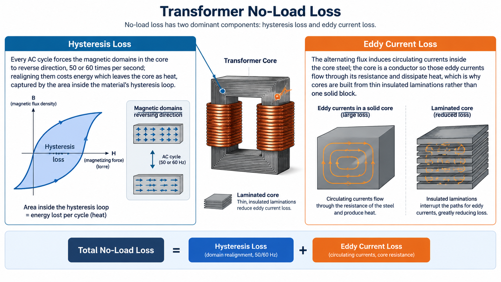
Every AC cycle forces the magnetic domains in the core to reverse direction, 50 or 60 times per second. Realigning them costs energy, which leaves the core as heat. The effect is captured by the area inside the material’s hysteresis loop: a narrow loop means low loss, which is why silicon steel and amorphous alloys replace plain iron.
2. Eddy Current Loss
The alternating flux also induces circulating currents inside the core steel. The core is a conductor, so those eddy currents flow through its resistance and dissipate heat. This is why cores are built from thin, insulated laminations rather than one solid block — splitting the core multiplies the resistance of the eddy current path.
3. Stray Core Loss
A minor component appears in clamps, bolts and tank walls, where leakage flux induces small circulating currents. It is why a finished core can measure higher loss than the raw steel grade alone suggests.
How to Calculate Transformer No-Load Loss
Method 1: The Component Formulas
- Hysteresis: Ph = kh × f × Bmn × G, where kh is a material constant, f is frequency, Bm is peak flux density, n is the Steinmetz exponent (roughly 1.6–2.5 for silicon steel), and G is core mass.
- Eddy current: Pe = ke × f² × Bm² × t² × G, where ke depends on material conductivity and t is lamination thickness.
Total no-load loss is P0 = Ph + Pe. Two points follow. Hysteresis loss scales with frequency, but eddy current loss scales with frequency squared, which is why 60 Hz and high-frequency designs diverge sharply. Eddy current loss also scales with the square of lamination thickness.
Method 2: The Open-Circuit Test
For specification work you rarely need first-principles derivation; the number you want is the tested value.
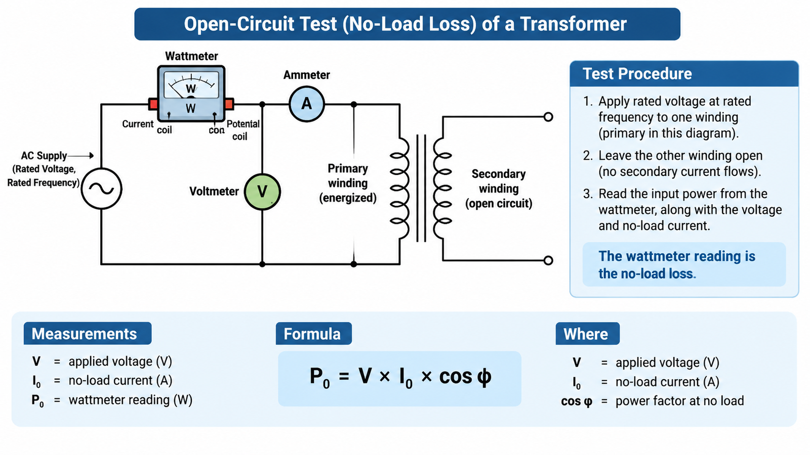
- Apply rated voltage at rated frequency to one winding.
- Leave the other winding open, so no secondary current flows.
- Read input power with a wattmeter, along with voltage and no-load current.
- The reading is the no-load loss: P0 = V × I0 × cos φ.
Before test data exists, a common estimate is 0.1–0.3% of rated capacity — a sanity check on a datasheet, not a substitute for measured values.
A Worked Example
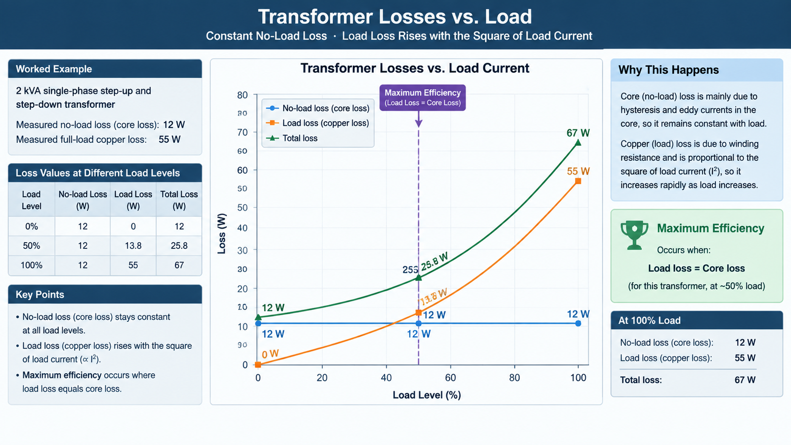
Take a 2 kVA single-phase transformateur élévateur et abaisseur with a measured no-load loss of 12 W and full-load copper loss of 55 W.
| Load level |
No-load loss |
Load loss |
Total loss |
| 0% |
12 W |
0 W |
12 W |
| 50% |
12 W |
13.8 W |
25.8 W |
| 100% |
12 W |
55 W |
67 W |
Extend that over time. At 24/7 operation the 12 W core loss alone consumes about 105 kWh per year. If the unit sits energized most of the year but carries load only a few hours a day, that constant component accounts for most of its annual energy consumption.
Efficiency follows the same data: output divided by output plus losses, so this unit delivers roughly 96.7% at full load and 96.2% at half load. Maximum efficiency occurs where load loss equals core loss — here, near 47% of rated load. That is why rated-load efficiency is not automatically the peak figure.
Why No-Load Loss Drives Total Cost of Ownership
Purchase price is a one-time number; no-load loss is recurring, running for the whole 20 to 30 year service life.
Compare two 1000 kVA units in the same price bracket — one with a conventional grain-oriented silicon steel core at 1.4 kW no-load loss, the other with an amorphous alloy core at roughly 0.45 kW. The 0.95 kW gap is about 8,300 kWh a year at continuous energization, close to $1,000 a year at $0.12 per kWh, for a difference invisible on the nameplate unless you look for P0. Over 20 years that energy loss dwarfs the price gap between the designs.
Core loss also appears as heat, raising insulation temperature and shortening life. If you are sizing against a load profile, our guide on why transformers are rated in kVA explains how capacity, power factor and losses interact.
How to Reduce No-Load Loss
Matériau de base
Material choice is the single largest lever.
| Core material |
Relative no-load loss |
Where it fits |
| Conventional grain-oriented silicon steel |
Baseline |
General-purpose, cost-sensitive builds |
| High-permeability low-loss silicon steel |
10–20% lower |
Balance of efficiency and price |
| Amorphous alloy |
60–75% lower |
Continuous-duty and lightly loaded equipment |
Construction de base
- Lamination thickness. Thinner laminations — around 0.23–0.27 mm for modern low-loss steel — cut eddy current loss substantially. Thicker gauges can roughly double it under identical test conditions.
- Joint design. Step-lap or mitered joints let flux cross the joint region smoothly; butt joints create high reluctance and localised loss.
- Flux density. Designing at lower peak flux density reduces loss and noise, at the cost of a larger core.
Core geometry is covered in our article on Construction des transformateurs et structure du noyau de fer.
Operating Practice
Where duty allows, de-energizing transformers that are not needed removes 100% of their no-load loss — the simplest and most complete measure available. Where continuous energization is unavoidable, voltage regulation matters: sustained over-voltage raises flux density and pushes both components above the tested value.
How to Read No-Load Loss on a Datasheet
Compare quotes on these fields, not on price and a “low-loss” label.
| What to compare |
Lower-loss signal |
Warning sign |
| Core material grade |
Named grade or amorphous alloy |
Grade omitted entirely |
| Measured no-load loss |
Unit-specific figure at rated voltage |
Only a per-kilogram steel figure quoted |
| Test conditions |
Voltage, frequency and temperature stated |
Conditions unstated, so figures are not comparable |
| Factory test report |
Per-unit report supplied |
Typical values only |
A comparison only holds when frequency and flux density match; a per-kilogram figure measured at lower flux density will always look better on paper.
Common Mistakes
- Assuming load loss is the bigger cost. At low loading, core loss dominates annual energy use — the opposite of what full-load calculations suggest.
- Comparing steel figures across unmatched test conditions. Frequency and flux density must match first.
- Treating rated-load efficiency as peak efficiency. Peak efficiency sits where copper loss equals core loss, typically well below rated load.
For duty cycles with long periods at partial load, check the thermal side too: our analysis of how to calculate transformer overload covers how sustained loading above nameplate affects winding temperature and insulation life.
Conclusion
No-load loss is the constant cost of keeping a transformer energized. It comes from hysteresis and eddy currents in the core, it does not respond to load, and it is measurable with a straightforward open-circuit test. For any unit that runs continuously, especially at light load, the tested P0 figure deserves as much attention as the kVA rating.
If you are specifying transformers for continuous or standby duty, the STU series 100VA to 2kVA is a practical starting point for low-power industrial and equipment-level applications. You can also browse the full step-up and step-down transformer range to match a rating to your load profile — or send us your duty cycle and we will tell you which core option pays back fastest.
FAQ
What is no-load loss in a transformer?
It is the active power a transformer draws when rated voltage is applied with no load connected to the secondary. Also called core loss or iron loss, it is present whenever the unit is energized and does not vary with load current. Because no-load current is only about 1–3% of rated current, the measured value is effectively the core loss.
How do I calculate transformer no-load loss?
Use the open-circuit test: apply rated voltage and frequency to one winding, leave the other open, and read input power with a wattmeter. Analytically, P0 = Ph + Pe.
Does no-load loss change with load?
No. It stays essentially constant from 0% to 100% load. Load loss is the component that changes, rising with the square of load current.
At what load does a transformer reach maximum efficiency?
Maximum efficiency occurs where load loss equals core loss, typically between 40% and 60% of rated load. That is why rated-load efficiency is not necessarily the peak value.
How can no-load loss be reduced?
Use lower-loss core material such as high-permeability silicon steel or amorphous alloy, use thinner laminations and step-lap joints, design at moderate flux density, and de-energize transformers that are not required.
Recommended Models for No-Load Loss and Efficiency
If you are specifying a unit rather than reading theory, start here. These models cover the capacity bands most often requested for no-load loss and efficiency, and each links straight to its specification and price range.
Tell us the input voltage, output voltage, phase and continuous kVA you need, and we will confirm the matching model, price and lead time within one business day. Non-standard ratings are handled through OEM/ODM custom transformer manufacturing.